Download
1 / 20
210 likes | 289 Views
Optimization of the Detector Arrangement of the ITER-FEAT Bolometric Diagnostic. S. Kalvin KFKI-Research Institute for Particle and Nuclear Physics Association EURATOM HAS. Contents. Tomographic method Method of testing Detector arrangement Effect of the measurements error

E N D
Optimization of the Detector Arrangement of the ITER-FEAT Bolometric Diagnostic S. Kalvin KFKI-Research Institute for Particle and Nuclear Physics Association EURATOM HAS
Contents • Tomographic method • Method of testing • Detector arrangement • Effect of the measurements error • Check the spatial resolution • Effect of the LOS number • Detector arrangement with no inner VV wall detectors • Effect of the neutral radiation
I. Starting points: I.1. Requirements for performance:
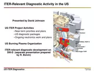
I.2. Technical possibilities of the detector arrangement: For divertor chamber For main plasma Vacuum vessel wall Upperport Equatorial port Filler socket Divertor casette Divertor casette Technically realistic solution ---Total number of LOS is about 300
II. Tomographic method A simple and stable first order regularization method was used. This method provides the flattest radiation profile which fits well to the measurement. II.1 The two dimensional radiation distribution is approximated by a weighted sum of the base functions.
II.2 Calculation of the measurement signals 40 – 60 –80 mm 60 mm
II.3. Regularization = 0.2 = 1
III. 1. Method of testing Calculate meas. signals Do the reconstruction Add noise to simulate the measurement error Compare the original and the reconstructed profile
IV.1. Considerations for the detector arrangement • In the main plasma and the divertor chamber the LOS should create uniform coverage which enables us to reach sufficient spatial resolution.The coverage fits to the required spatial resolution both in the main chamber and the divertor chamber. • The toroidal dispersion of the detectors was due to a requirement to distribute and rationalize the cabling in the vacuum vessel and the divertor cassette. • There is a section, where the number of detectors is large enough (sector #16). The LOS in this section should be arranged in a way to perform a “good” quality reconstruction using only these detectors. Detectors of other sections can be used to check the toroidal symmetry of the plasma radiation or can be used to improve the reconstruction quality in the toroidally symmetric case. • In order to discriminate the neutrals from the photons a few LOS are directed toward the divertor chamber through the main plasma.
IV.2. The proposed detector arrangement Total: 33 detectors 165 LOS Total: 30 detectors 150 LOS
V.1. Effect of the measurement error Main plasma tomography Divertor chamber tomography
V.2. Conclusion --Effect of the measurement error The measurement error contains: • The electrical noise • Manufacturing error of the detector head • Positioning error of the detector to ITER • Calibration error • The total error has to be less than few percentage. • The individual channels have to be relatively calibrated very accurately
VI. Check of the spatial resolution 50 cm 10 cm Main plasma Divertor chamber
VII.1. The effect of the LOS number on the reconstruction quality Main plasma tomography Divertor chamber tomography
VII.2. Case of insufficient LOS number Error of rad. Power:1.2%
VII.3. Conclusion: the effect of the LOS number … • There is enough redundancy to compensate the decrease of the LOS due to failure of • the channels. • We have to know the correct failure rate to design the amount of redundancy. Tests with no inner VV wall detectors The distributed inner vacuum vessel detectors might be removed from the bolometer system (should be further investigated).
IX.1. Effect of the neutral radiation The amount of the neutral radiation will not be negligible. The metal foil bolometer is sensitive to this radiation. There are two ways to overcome this problem: 1. To develop a detector which is insensitive to the neutral radiation. 2. Software solution. We suppose: -- the neutral radiation in the main chamber is much lower than in the divertor , -- the neutrals completely absorbed by the main plasma so the detectors looking through the main plasma to the divertor chamber do not detect any neutrals, + regularization tomography
IX.2. Tomographic reconstruction in the presence of neutral radiation The neutral radiation is not taken into account during the reconstruction. The neutral radiation is taken into account Flux of neut. /flux of E.M < 50 % Error of tot. rad. :7% Error of neut. Sig:4%