Download
1 / 23
230 likes | 310 Views
Preliminary Experimental Results on surpassing the diffraction limit for crossed optical axes . Implications

E N D
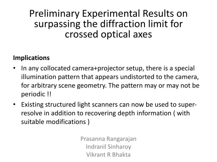
Preliminary Experimental Results on surpassing the diffraction limit for crossed optical axes Implications • In any collocated camera+projector setup, there is a special illumination pattern that appears undistorted to the camera, for arbitrary scene geometry. The pattern may or may not be periodic !! • Existing structured light scanners can now be used to super-resolve in addition to recovering depth information ( with suitable modifications ) • PrasannaRangarajan • IndranilSinharoy • Vikrant R Bhakta
Picture of Experimental Setup Target • Angle between optical axes of camera and projector is ≈ 30 degrees • The projector center-of-perspective is designed to be in the XZ plane of the camera coordinate system, which is centered at the camera center-of-perspective horizontally collocated setup Projector Optical Axis Camera Camera Optical Axis Baseline Projector Top View Side View • Special thanks to Indranil for the pictures
Picture of Experimental Setup Target • The target is parallel to the camera image plane during calibration • In all other cases, the target is parallel to the projector. Consequently, the camera perceives the calibration target as being tilted, and having depth variation Camera Projector Top View Side View • Special thanks to Indranil for the pictures
EXPERIMENT - 1 • USAF target positioned in front of calibration target such that it is parallel to the projector image plane • Illuminate scene with pre-warped vertical pattern of spatial frequency 90 cycles/mm in camera image plane Pre-warped illumination pattern 1400 x 1050 ( appears aliased due to MATLAB display issues ) Zoomed-in view of pre-warped illumination pattern 201x 201 patch Notice the perspective warp in illumination pattern
super-resolving a planar USAF target that is oriented at an angle of 30 degrees w.r.t camera • Notice the perspective distortion in the image of the USAF target • camera optical cutoff ≈ 180 lp/mm in the image plane • size of image is 601 x 601
super-resolving a planar USAF target that is oriented at an angle of 30 degrees w.r.t camera • Notice the periodic pattern super-imposed on the USAF target. Although the target appears to experience perspective distortion, the pattern appears un-distorted to the camera ( evident in the Fourier domain ) • carrier frequency ≈ 90 lp/mm in the camera image plane
super-resolving a planar USAF target that is oriented at an angle of 30 degrees w.r.t camera • Notice that modulation is able to resolve vertical edges in the oriented USAF target • NOTE: The carrier pattern might appear slightly aliased due to MATLAB’s display issues • The fringe patterns on the target appear oriented due to the tilt in the target
super-resolving a planar USAF target that is oriented at an angle of 30 degrees w.r.t camera • Notice the peak in the fourier spectrum of the cosine/sine modulated image of the scene, at ≈ 90 lp/mm in the camera image plane
super-resolving a planar USAF target that is oriented at an angle of 30 degrees w.r.t camera • Notice the peak in the fourier spectrum of the complex sinusoidal modulated image of the scene, at ≈ 90 lp/mm in the camera image plane
super-resolving a planar USAF target that is oriented at an angle of 30 degrees w.r.t camera • Notice that modulation in the vertical direction is able to extend the bandwidth of the imaging system in the vertical direction
super-resolving a planar USAF target that is oriented at an angle of 30 degrees w.r.t camera • size of raw image is 601 x 601
super-resolving a planar USAF target that is oriented at an angle of 30 degrees w.r.t camera • size of super resolved image is 841 x 841 • Notice enhanced resolution in vertical elements of group -1 ( zoom-in for better view ) There is a faint artifact that is regular and appears to be perspectively distorted
EXPERIMENT - 2 • Barcode target positioned in front of calibration target such that it is parallel to the projector image plane • Illuminate scene with pre-warped vertical pattern of spatial frequency 90 cycles/mm in camera image plane Pre-warped illumination pattern 1400 x 1050 ( appears aliased due to MATLAB display issues ) Zoomed-in view of pre-warped illumination pattern 201x 201 patch Notice the perspective warp in illumination pattern
super-resolving a planar barcode target that is oriented at an angle of 30 degrees w.r.t camera • Notice the perspective distortion in the image of the barcode target • camera optical cutoff ≈ 180 lp/mm in the image plane • size of image is 601 x 601 • the fine spatial in the barcodes is missing ( zoom-in for better view )
super-resolving a planar USAF target that is oriented at an angle of 30 degrees w.r.t camera • Notice the periodic pattern super-imposed on the USAF target. Although the target appears to experience perspective distortion, the pattern appears un-distorted to the camera ( evident in the Fourier domain ) • carrier frequency ≈ 90 lp/mm in the camera image plane
super-resolving a planar USAF target that is oriented at an angle of 30 degrees w.r.t camera • Notice that modulation is able to resolve vertical edges in the 1D & 2D barcodes • NOTE: The carrier pattern might appear slightly aliased due to MATLAB’s display issues • The fringe patterns in the barcodes appear oriented due to the tilt in the target
super-resolving a planar barcode target that is oriented at an angle of 30 degrees w.r.t camera • Notice the peak in the fourier spectrum of the cosine/sine modulated image of the scene, at ≈ 90 lp/mm in the camera image plane
super-resolving a planar barcode target that is oriented at an angle of 30 degrees w.r.t camera • Notice the peak in the fourier spectrum of the complex sinusoidal modulated image of the scene, at ≈ 90 lp/mm in the camera image plane
super-resolving a planar barcode target that is oriented at an angle of 30 degrees w.r.t camera • Notice that modulation in the vertical direction is able to extend the bandwidth of the imaging system in the vertical direction
super-resolving a planar barcode target that is oriented at an angle of 30 degrees w.r.t camera • size of raw image is 601 x 601
super-resolving a planar barcode target that is oriented at an angle of 30 degrees w.r.t camera • size of super resolved image is 841 x 841 • Notice enhanced resolution in the vertical barcode & the 2D bar code • The vertical barcode is fully resolved There is a faint artifact that is regular and appears to be perspectively distorted