Download
1 / 42
420 likes | 539 Views
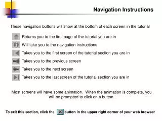
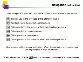
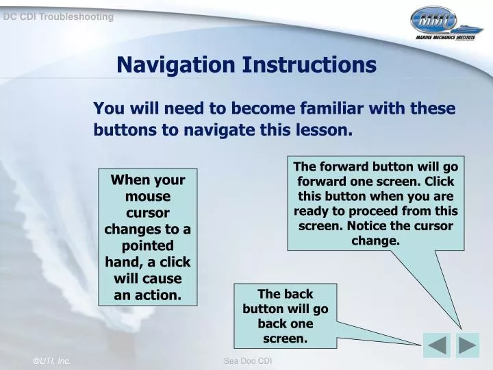
Navigation Instructions. You will need to become familiar with these buttons to navigate this lesson. The forward button will go forward one screen. Click this button when you are ready to proceed from this screen. Notice the cursor change.

E N D
Navigation Instructions You will need to become familiar with these buttons to navigate this lesson. The forward button will go forward one screen. Click this button when you are ready to proceed from this screen. Notice the cursor change. When your mouse cursor changes to a pointed hand, a click will cause an action. The back button will go back one screen.
Objectives The participants will identify components and testing procedures for a Sea Doo Battery Powered Ignition system. This will be demonstrated by the participants completing a written exam with 80 percent accuracy.
Systematic Approach To insure an efficient and accurate diagnosis, the following systematic approach must be used: • Battery inspection • MPEM advanced diagnostic test • Spark test • MPEM CDI Output Test • Trigger Coil Output Test
1. Battery Inspection • The first step is to insure that the craft has a fully charged battery . • Battery service should begin with a thorough visual inspection: • Check for cracks in the battery case and broken terminals. • Check for cracked or broken cables. • Check for loose battery cable connections.
Battery Inspection (cont’d) • Visual inspection (cont’d): • Check the electrolyte fluid level. • Check for cloudy or discolored electrolyte caused by overcharging or vibration.
Battery Load Test (cont’d) • The next step is to perform a battery load test. • A battery load tester provides important information consisting of open battery voltage, voltage under load and internal resistance.
Battery Load Test (cont’d) • Battery Load Testing procedures: • Install the load tester in parallel with the battery. • Load the battery by turning the load increase control until the ammeter reads 3 times the amp-hour rating of the battery. • Maintain the load for 15 seconds, and note the voltmeter reading.
Battery Load Test (cont’d) If the voltmeter reading during 15 second test is: • 9.6 volts or higher, the battery is good. • 9.5 volts or lower, the battery is defective and needs replacement.
2. MPEM advanced diagnostic test • The next step is the MPEM diagnostic test. • Start by removing the safety lanyard from DESS post. • Press 5 times on the watercraft start/stop button. • 1 short beep and 1 long beep must be heard (they validate beginning of diagnostic mode).
MPEM advanced diagnostic test • Install safety lanyard on watercraft DESS post. • Press the watercraft start/stop button again. • If everything is correct, the engine will start. • Otherwise, refer to the following chart.
MPEM advanced diagnostic test • If no beeps occur and the engine does not start or crank over, then test for battery voltage at the MPEM. • Meter connection: • Positive meter lead to Amphenol connecter number 3, pin 26 • Negative meter lead to Amphenol connecter number 3, pin 24
Amphenol Connector #3 Pin #24 Pin #26
Amphenol Connector #3 Pin #24 Pin #26
MPEM advanced diagnostic test • If battery voltage is not present at the Amphenol connector, then test the main battery fuse. • If the main battery fuse checks okay, then use a test light to trace the wire for an open.
3. Spark Test • The next step is to test for strong, quality spark that will fire the spark plugs under compression. • A neon spark tester should be used for this test. Picture of neon tester here
3. Spark Test (cont’d) • Install the neon testers in series with the high tension leads. • While cranking the engine, observe for spark on both cylinders. Observe for spark in the neon spark testers
3. Spark Test (cont’d) • If spark occurs in both cylinders then the ignition system is operating properly and no other tests are needed. • If spark does not occur in either cylinder, then an ignition system failure is present.
Direct Voltage Adapters • The input or output voltages of the remaining ignition system tests are pulse voltages. • Ignition pulse voltages increase and decrease within extremely short periods of time and can not be tested with a typical volt meter.
Peak Voltage Adapters (cont’d) • Rather than using an expensive oscilloscope, which is suitable for measuring short-length pulses, the marine industry utilizes a direct voltage adapter (DVA). • The DVA must be used with a commercially available digital multimeter (impedance 10M/DCV minimum).
4. MPEM CDI Output Test • The 4th step is to check for CDI output. • The CDI output of the MPEM should be 100 volts or higher at engine cranking speeds. • CDI output is checked at the ignition coil. • Proper connection to the ignition coil is imperative, the correct polarity must be observed.
While cranking the engine the meter reading should be 100 volts or more Need picture showing meter reading of 100 plus volts
MPEM CDI Output Test (cont’d) • If the peak voltage is lower than 100 volts, reverse the meter leads and recheck the peak voltage. • If the peak voltage is still lower than specifications, disconnect the ignition coil’s primary leads and test again. • If the peak voltage is still lower than specification, reverse the meter leads again.
MPEM CDI Output Test (cont’d) • If the voltage reading is 100 volts or more, then the ignition system from the MPEM back is operating properly, and the problem is in the ignition coil area. • If the voltage reading is 100 volts or more only with the MPEM disconnected from the ignition coil, then the problem is in the ignition coil area. • If the voltage reading is less than 100 volts, then the MPEM is defective and must be replaced.
5. Trigger Coil Output Test • The last step in the systematic troubleshooting procedures is testing the output of the trigger coil. • The output of the Trigger coil is typically 3 to 4 volts at engine cranking speeds • In order to test trigger coil output a 6-pin break-out harness is needed • The 6-pin break-out harness is connected in series with the magneto Deutsch connector
6-pin break out harness Magneto Deutsch connector
Trigger Coil Output Test (cont’d) • Proper meter connection to the trigger coil is imperative (see next slide). • The output of the Trigger coil is typically 3 to 4 volts at engine cranking speeds
Sea Doo 6-pin break out harness DVA Meter Leads
While cranking the engine, the meter reading should read between 3 and 4 volts.
Trigger Coil Output Test (cont’d) • If the peak voltage is lower than 3 volts, reverse the meter leads and recheck the peak voltage. • If the peak voltage is still lower than specifications, disconnect the trigger coils leads and test again. • If the peak voltage is still lower than specification, reverse the meter leads again.
Trigger Coil Output Test (cont’d) • If the voltage reading is between 3 and 4 volts, then the trigger coil is operating properly. • If the voltage reading is between 3 and 4 volts only with the trigger coil disconnected, then the problem is in the MPEM. • If the voltage reading is less than 3 volts, then the trigger coil is defective.