Download
1 / 24
240 likes | 350 Views
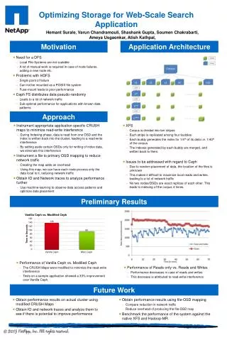
CALICE Si-W EM calorimeter Preliminary Results of the testbeams 2006 1 st part. On behalf of the CALICE Collaboration. Why doing testbeam. Calorimetry for ILC: mostly driven by Particle Flow performance to achieve Optimum design addressed by MC simulation

E N D
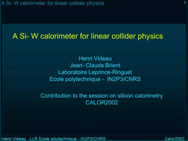
CALICE Si-W EM calorimeterPreliminary Results of the testbeams 20061st part On behalf of the CALICE Collaboration
Why doing testbeam • Calorimetry for ILC: mostly driven by Particle Flow performance to achieve • Optimum design addressed by MC simulation Need to validate the simulation against a realistic detector ! • And it allows to discover design/hardware issues in time to solve them. current performance for LDC-like detectors typical LEP-detectors performance see Mark Thomson’s talk today LCWS 2007 ----- Hamburg ----- A.-M. Magnan (IC London)
Layout Introduction: the ECAL prototype • the testbeam setups • Calibration procedure • Pedestal and noise and crosstalk issues • Electron selection for the analyses • Tracking resolution at ECAL front face Conclusion LCWS 2007 ----- Hamburg ----- A.-M. Magnan (IC London)
The Electromagnetic Calorimeter prototype 200mm • 6x6 1x1cm2 Si pads • Conductively glued to PCB 360mm 360mm Active area of 12*18 cm2 completed for 30 layers Last 1/3rd : expected by July 2007, ~50% already completed 62 mm 62 mm • W layers wrapped in carbon fibre or between 2 PCBs • Total tungsten thickness = 24 X0. • PCB+Si layers:8.5 mm • ECAL prototype: • 3 modules with variable thickness of Tungsten • Active slabs with silicon layers+tungsten interleaved • Front end chip and readout on PCB board Detailed implementation in the Geant4-based simulation for ILC: MOKKA (v06-03) Output data format: LCIO. LCWS 2007 ----- Hamburg ----- A.-M. Magnan (IC London)
CERN TB area, with 30 layers. ECAL+AHCAL: 1.7 M triggers, pions beam, 5 energies (30-80 GeV), 3 angles, ECAL alone: 8.6 M triggers, electron beams, 6 energies (10-45 GeV), 4 angles, + 30 Million muons for calibration. Aug 25th Sept 6th CERN TB area. Combined ECAL+AHCAL + TCMT: e+, e-: 3.8 M triggers, 10 energies (6-45 GeV) π+,π-: 22 M triggers, 11 energies (6-80 GeV) + 40 Million muons for calibration. Oct 11th Oct 30th I- Overview of last year TB DESY TB area, with only 24 layers . 14 days in total ~8 Million triggers, 7 energies (1-6 GeV), 5 angles, 3 positions May LCWS 2007 ----- Hamburg ----- A.-M. Magnan (IC London)
Testbeam setup in DESY LCWS 2007 ----- Hamburg ----- A.-M. Magnan (IC London)
Testbeam setup in CERN - August LCWS 2007 ----- Hamburg ----- A.-M. Magnan (IC London)
Testbeam setup in CERN - October 10 GeV pion event, taken Oct 16th 2006 LCWS 2007 ----- Hamburg ----- A.-M. Magnan (IC London)
μ calib. August period Sept. break October period μ calib. runs Summary of the data taken • Size on disk: ~ 40 kB/evt • 65M events = 2.5 TB for CERN Physics runs • + 70 M = 3 TB for muon calibration runs All the reconstruction has been done using the GRID ! LCWS 2007 ----- Hamburg ----- A.-M. Magnan (IC London)
II- ECAL calibration • Using muon runs taken in October: ~18M events • Taken with another experiment upstream wide spread muon beam • Procedure: • reject noise with a fixed cut at 25 ADC counts (~0.5MIP) • selection of MIP-like tracks : 15 ≤Nhits ≤ 40, in a 2 cm tower • fit with a Landau convoluted with a Gaussian • only 9 dead channels: 1.4‰ !! • 6403/6471 : 98.9% convergent fit. • 18/6471 needed a special treatment because of high noise. • 14/6471 have been calibrated thanks to their neighbours. • One wafer (=36 cells) with a relative calibration : appears to be not fully depleted, 0.517×normal signal !! 6471 calibrated channels Mean : 45.5 ADC counts RMS : 2.2 ADC counts LCWS 2007 ----- Hamburg ----- A.-M. Magnan (IC London)
III- Pedestal, noise and crosstalk issues1- Square events : crosstalk with guard ring LCWS 2007 ----- Hamburg ----- A.-M. Magnan (IC London)
2- Pedestal instabilities Ex: Muon run (ECAL threshold : 0.5 MIP) A Good PCB • NEW !!Understood : fake differential in the chip due to instabilities of the power supply not compensated. Is corrected in the EUDET module (SKIROC chip) pedestal noise A PCB with unstable pedestals LCWS 2007 ----- Hamburg ----- A.-M. Magnan (IC London)
Total signal in the chip = 350 MIP Correlation between pedestal shift and signal recorded 4 MIP shift ~ 200 ADC counts Pedestal shift (ADC counts) 3- Small signal in same wafer 1- Pedestal substracted signal of all pads of one PCB 2- Beam hit the second wafer (chips #2 and #3) signal (ADC counts) 3- Signal induced pedestal shift: crosstalk @ wafer scale The effect • Not understood yet • under investigation • Correlated with signal intensity • Affects a few wafers randomly in space and time… 1 chip = 18 channels 2 chips = 1 wafer LCWS 2007 ----- Hamburg ----- A.-M. Magnan (IC London)
Pedestal instabilities: corrected event by event by iterating on the mean and RMS in wafers without signal <corr> = 0.07 ± 0.04 Correlation between 2 channels, per wafer. 0% 50% 80% 100% <corr> = 0.32 ± 0.16 -100% 0% 50% 100% After all corrections in wafer recording a signal: • Signal Induced Pedestal Shift: • corrected event by event by iterating on the channels having no signal but in a wafer recording a signal. • position of the signal: less cells to perform the calculation=less correlations… For completeness : a wafer only affected by signal induced shift: <corr> = 0.06 ± 0.07 <corr> = 0.06 ± 0.02 <corr> = 0.21 ± 0.09 <corr> = 0.42 ± 0.19 Impact on the noise andsoftware correction procedure PCB layer 9 in 6 GeV e- run (DESY) Wafers of the middle row before any corrections Wafers of the middle row after corrections <corr> = 0.72 ± 0.02 <corr> = 0.66 ± 0.10 <corr> = 0.77 ± 0.02 36*36 channels Corrections are doing their job pretty well !! LCWS 2007 ----- Hamburg ----- A.-M. Magnan (IC London)
Noise after all corrections Extracted from 11 runs at different energies Mean noise @ CERN ±3% LCWS 2007 ----- Hamburg ----- A.-M. Magnan (IC London)
IV- Electron selection • Triggering : coincidence of 3 scintillators along the beam line. • Signal threshold: 0.6 MIP • Selection of single electron events: • CERN: Čerenkov counter to remove pion contamination • DESY : shower barycentre in the region expected from the beam profile. LCWS 2007 ----- Hamburg ----- A.-M. Magnan (IC London)
Data/MC comparison • High energy tails very well reproduced, also up to 1.5 MIP • Low energy disagreement not yet understood, under investigation • But little influence on the total energy present analyses based on the energy. 30 GeV electrons Pion 12 GeV not showering in the ECAL set the global energy scaling for the MC 30 GeV electrons linear scale LCWS 2007 ----- Hamburg ----- A.-M. Magnan (IC London)
V- Tracking performances @ ECAL front face • In view of extracting the ECAL resolution, need to subtract the tracking resolution • Tracking: best linear fit with 4 chambers is considered to give the expected position and direction at ECAL front face. • Error matrix contains intrinsic chambers resolution and scattering in front of the ECAL. • Systematic errors in extrapolation to ECAL front face directly affects ECAL estimates. LCWS 2007 ----- Hamburg ----- A.-M. Magnan (IC London)
Results for the tracking resolution ECAL front face x,y σpos * σangle z beam LCWS 2007 ----- Hamburg ----- A.-M. Magnan (IC London)
Introduction’s conclusions • Testbeams 2006 have been a complete success: • discovery of hardware problems: • capacitance issues giving raise to so-called “square events”, • Importance of compensating power supplies for the stability of pedestal lines, • … and more to come ! Crosstalk issue affecting pedestals at wafer scale ?? • exercise real life detectors and data handling: e.g. GRID setup, reconstruction software, simulation and digitisation issues. • allowed to improve already the detector simulation models. • lots of data taken, with a full spectrum in energy, angle, position • Really good training for coming testbeam with a completed prototype : summer 2007, starting in 3 weeks. • learning from our mistakes : even more efficient shift organisation + faster analyses and feedback expected. • Preliminary results on performance presented by C. Carloganu right now ! LCWS 2007 ----- Hamburg ----- A.-M. Magnan (IC London)
Thank you for your attention LCWS 2007 ----- Hamburg ----- A.-M. Magnan (IC London)
Backup LCWS 2007 ----- Hamburg ----- A.-M. Magnan (IC London)
Detailed view of ECAL PCB LCWS 2007 ----- Hamburg ----- A.-M. Magnan (IC London)
noise after corrections LCWS 2007 ----- Hamburg ----- A.-M. Magnan (IC London)