Download
1 / 47
470 likes | 478 Views
The Path Toward a Linear Collider. Barry Barish HEP 2005 Lisbon, Portugal 23-July-05. The ITRP Recommendation. We recommend that the linear collider be based on superconducting rf technology

E N D
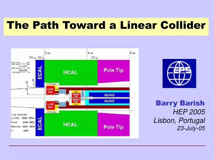
The Path Toward a Linear Collider Barry Barish HEP 2005 Lisbon, Portugal 23-July-05
The ITRP Recommendation • We recommend that the linear collider be based on superconducting rf technology • This recommendation is made with the understanding that we are recommending a technology, not a design. We expect the final design to be developed by a team drawn from the combined warm and cold linear collider communities, taking full advantage of the experience and expertise of both(from the Executive Summary). HEP 2005 - Barish
The Community then Self-Organized Nov 13-15, 2004 HEP 2005 - Barish
The First ILC Meeting at KEK There were 220 participants divided among 6 working groups Working Group 1: Overall Design Working Group 2: Main Linac Working Group 3: Injector, including damping rings Working Group 4: Beam Delivery Systems, including collimator, final focus, etc. Working Group 5: Cavity design: higher gradients, .. Working Group 6: Strategic communication Each working group had three convenors, one from each region HEP 2005 - Barish
Formal organization begun at LCWS 05 at Stanford in March 2005 when I became director of the GDE The Global Design Effort Technically Driven Schedule
GDE – Near Term Plan • Staff the GDE • Administrative, Communications, Web staff • Regional Directors (one per region) • Engineering/Costing Engineer (one per region) • Civil Engineer (one per region) • Key Experts for the GDE design staff from the world community • Fill in missing skills (later) Total staff size about 20 FTE (2005-2006) HEP 2005 - Barish
GDE – Near Term Plan • Organize the ILC effort globally • First Step --- Appoint Regional Directors within the GDE who will serve as single points of contact for each region to coordinate the program in that region. (Gerry Dugan (North America), Fumihiko Takasaki (Asia), Brian Foster (Europe)) • Make Website, coordinate meetings, coordinate R&D programs, etc • R&D Program • Coordinate worldwide R & D efforts, in order to demonstrate and improve the performance, reduce the costs, attain the required reliability, etc. (Proposal Driven to GDE) HEP 2005 - Barish
GDE – Near Term Plan • Schedule • Begin to define Configuration (Aug 05) • Baseline Configuration Document by end of 2005 ----------------------------------------------------------------------- • Put Baseline under Configuration Control (Jan 06) • Develop Reference Design Report by end of 2006 • Three volumes -- 1) Reference Design Report; 2) Shorter glossy version for non-experts and policy makers ; 3) Detector Concept Report HEP 2005 - Barish
Snowmass Workshop – Aug 2005 HEP 2005 - Barish
Snowmass – GDE Takes Over HEP 2005 - Barish
Design Issues HEP 2005 - Barish
Starting Point for the GDE Superconducting RF Main Linac HEP 2005 - Barish
Some Key Near-Term Design Choices • Accelerating Gradient • Positron Production mechanism • Design of Damping ring • Site-specific considerations: One or two tunnels? Shallow or deep?, etc • Total cost will be a key determining factor in our ability to get the ILC built. Therefore cost optimization of all systems is of primary importance HEP 2005 - Barish
Towards the ILC Baseline Design HEP 2005 - Barish
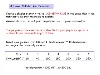
Parameters for the ILC • Ecm adjustable from 200 – 500 GeV • Luminosity ∫Ldt = 500 fb-1 in 4 years • Ability to scan between 200 and 500 GeV • Energy stability and precision below 0.1% • Electron polarization of at least 80% • The machine must be upgradeable to 1 TeV HEP 2005 - Barish
Specific Machine Realizations • rf bands: • L-band (TESLA) 1.3 GHz l = 3.7 cm • S-band (SLAC linac) 2.856 GHz 1.7 cm • C-band (JLC-C) 5.7 GHz 0.95 cm • X-band (NLC/GLC) 11.4 GHz 0.42 cm • (CLIC) 25-30 GHz 0.2 cm • Accelerating structure size is dictated by wavelength of the rf accelerating wave. Wakefields related to structure size; thus so is the difficulty in controlling emittance growth and final luminosity. • Bunch spacing, train length related to rf frequency • Damping ring design depends on bunch length, hence frequency Frequency dictates many of the design issues for LC HEP 2005 - Barish
Cost Breakdown by Subsystem Civil SCRF Linac HEP 2005 - Barish
What Gradient to Choose? HEP 2005 - Barish
TESLA Cavity ~1m 9-cell 1.3GHz Niobium Cavity Reference design: has not been modified in 10 years HEP 2005 - Barish
Electro-polishing (Improve surface quality -- pioneering work done at KEK) BCP EP • Several single cell cavities at g > 40 MV/m • 4 nine-cell cavities at ~35 MV/m, one at 40 MV/m • Theoretical Limit 50 MV/m HEP 2005 - Barish
Gradient Results from KEK-DESY collaboration must reduce spread (need more statistics) single-cell measurements (in nine-cell cavities) HEP 2005 - Barish
How Costs Scale with Gradient? 35MV/m is close to optimum Japanese are still pushing for 40-45MV/m 30 MV/m would give safety margin Relative Cost Gradient MV/m C. Adolphsen (SLAC) HEP 2005 - Barish
Gradient HEP 2005 - Barish
Evolve the CavitiesMinor Enhancement Low Loss Design Modification to cavity shape reduces peak B field. (A small Hp/Eacc ratio around 35Oe/(MV/m) must be designed). This generally means a smaller bore radius Trade-offs (Electropolishing, weak cell-to-cell coupling, etc) KEK currently producing prototypes HEP 2005 - Barish
New Cavity Design Re-entrant 28 cell Super-structure More radical concepts potentially offer greater benefits. But require time and major new infrastructure to develop. single-cell achieved45.7 MV/m Q0 ~1010 (Cornell) HEP 2005 - Barish
Experimental Status single cell HEP 2005 - Barish
ILC Siting and Civil Construction • The design is intimately tied to the features of the site • 1 tunnels or 2 tunnels? • Deep or shallow? • Laser straight linac or follow earth’s curvature in segments? • GDE ILC Design will be done to samples sites in the three regions • North American sample site will be near Fermilab • Japan and Europe are to determine sample sites by the end of 2005 HEP 2005 - Barish
1 vs 2 Tunnels • Tunnel must contain • Linac Cryomodule • RF system • Damping Ring Lines • Save maybe $0.5M • Issues • Maintenance • Safety • Duty Cycle HEP 2005 - Barish
Fermilab ILC Civil Program A Fermilab Civil Group is collaborating with SLAC Engineers and soon with Japanese and European engineers to develop methods of analyzing the siting issues and comparing sites. The current effort is not intended to select a potential site, but rather to understand from the beginning how the features of sites will effect the design, performance and cost HEP 2005 - Barish
Parameters of Positron Sources HEP 2005 - Barish
Positron source Conventional source Undulator-based source B=0.75 T 5 mm gap HEP 2005 - Barish
Laser Compton Source HEP 2005 - Barish
Fast Kicker Development HEP 2005 - Barish
ILC Strawman Layout tuneup dump lines 20 mrad ILC FF9 (x 4) Mark Woodley HEP 2005 - Barish
Beam Delivery Systems -- Challenges • Transport the high-energy beam from the end of the main linac to the interaction point • Transport the post-collision spent beam and beamstralung to the dumps • Provide collimation for control of backgrounds • Provide machine protection systems for errant beams • Provide collision point maintenance through the use of fast feedback systems (inter-train and intra-train) HEP 2005 - Barish
Accelerator Physics Challenges • Develop High Gradient Superconducting RF systems • Requires efficient RF systems, capable of accelerating high power beams (~MW) with small beam spots(~nm). • Achieving nm scale beam spots • Requires generating high intensity beams of electrons and positrons • Damping the beams to ultra-low emittance in damping rings • Transporting the beams to the collision point without significant emittance growth or uncontrolled beam jitter • Cleanly dumping the used beams. • Reaching Luminosity Requirements • Designs satisfy the luminosity goals in simulations • A number of challenging problems in accelerator physics and technology must be solved, however. HEP 2005 - Barish
Test Facility at SLAC HEP 2005 - Barish
e- beam diagnostics e- beam diagnostics bunch compressor laser driven electron gun undulator photon beam diagnostics pre-accelerator superconducting accelerator modules TESLA Test Facility Linac - DESY 240 MeV 120 MeV 16 MeV 4 MeV HEP 2005 - Barish
Fermilab ILC SCRF Program HEP 2005 - Barish
Test Facility at KEK HEP 2005 - Barish
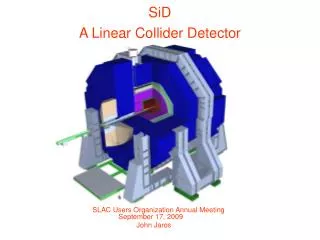
Beam Detector Interface Tauchi LCWS05 HEP 2005 - Barish
Detector Concepts and Challenges • Three concepts under study • Typically requires factors of two improvement in granularity, resolution, etc. from present generation detectors • Focused R&D program required to develop the detectors -- end of 2005 • Detector Concepts will be used to simulate performance of reference design vs physics goals next year. HEP 2005 - Barish
The GDE Plan • The Machine • Accelerator baseline configuration will be determined and documented (BCD) by the end of 2005 • R&D program and priorities determined (proposal driven) • Baseline configuration will be the basis of a reference design done in 2006 • The Detector(s) • Determine features, scope: one or two, etc (same time scale) • Measure performance of the baseline design • Beam delivery system and machine detector interfaces • Define and motivate the future detector R&D program HEP 2005 - Barish
Conclusions • The effort to make a global design for the linear collider is underway. choice of technology for main linac made the global design effort is underway baseline will be determined by the end of 2005 reference design next year (with costs) technical design will follow • We are on track produce a solid design and proposal to build an International Linear Collider within the next few years. HEP 2005 - Barish