Download
1 / 1
10 likes | 171 Views
05’. 05’. 72 o 00’. 72 o 00’. 55’. 55’. 50’. 50’. 45’. 45’. 40’. 40’. N a u t I c a l M I l e s. Chapter 3 – 1. North American Datum of 1983. (World Geodetic System 1984). Ruins. Cable Area. SOUNDINGS IN FEET. At Mean Lower Low Water. RG ”D”. Scale: 1:115,000. Fl(2+1)R”.

E N D
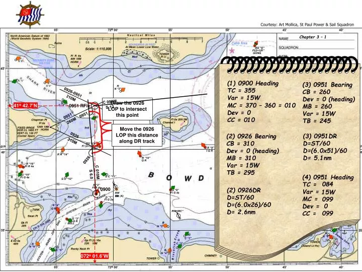
05’ 05’ 72o 00’ 72o 00’ 55’ 55’ 50’ 50’ 45’ 45’ 40’ 40’ N a u t I c a l M I l e s Chapter 3 – 1 North American Datum of 1983 (World Geodetic System 1984) Ruins Cable Area SOUNDINGS IN FEET At Mean Lower Low Water RG ”D” Scale: 1:115,000 Fl(2+1)R” GONG TOWER Fl R 6s Mud R Lt 40ft 10M SECURITY ZONE HORN 165.1155 note A) (see 45’ 45’ Cl stk Fl 8s Duttons I 42ft 8M R N “2” St COL REG DEMARCATION LINE R “4” G Fl R 6s C “3” BELL G Sh C “1’ Foul ! ! ! ! ! ! ! ! ! Fl 8s 20ft 5M Chapman Pt Channel I Fl 6s 126ft 18M FIXED BRIGE hrd HORN HOR CL 1800 FT Wd VERT CL 135 FT SD (Center Span) R “6” RG “CP” Fl R 4s Fl (2+1) R 6s 41o 40’ 41o 40’ R “8” BELL I Q R R N “14” R ”10” G “3” Q R Q R R “16” G “3” Fl R 4s Fl G 4s G Kelp GONG G “15” G C “11” Fl G 4s G C “13” R “2” Fl R 4s G “9” RW OR Fl G 4s G “7” Mo (A) Rks RANGE Fl G 4s G “1” Fl G 2s G R “4” C “1” RIVER R Q R Fl G 6s TANK N “2” rky RW “BC” OYSTER 24ft 5M “3” Rks Fl R 6s Swan Pt 24ft 5M “4” Bkw SPIRE G “3” Q R R Qk Fl R BELL Lts in line 245o 20ft N “2” 22FT 2002 G 35’ 35’ C “7” G R C r e e k N ”6” C “1” G Perkins Cove Gp Fl (2) 10s E Int 6s RIVER C “3” TOWER R 23ft 10M 40ft (Aband Lt Ho) N “6” G R Rocky Neck Pt Bl a c k f I s h C “5” N “4” Haven Bluff OYSTER CHIMNEY TOWER Courtesy: Art Mollica, St Paul Power & Sail Squadron (1) 0900 Heading TC = 355 Var = 15W (3) 0951 Bearing CB = 260 Dev = 0 (heading) MB = 260 Var = 15W TB = 245 0926-0951 310M Draw the 0926 LOP to intersect this point C 099M MC = 370 – 360 = 010 Dev = 0 CC = 010 41o 42.7’N 0951 RFix S 12 0951 0951 260M Move the 0926 LOP this distance along DR track Measure distance between DR’s (3) 0951DR D=ST/60 D=(6.0x51)/60 D= 5.1nm (2) 0926 Bearing CB = 310 Dev = 0 (heading) MB = 310 Var = 15W TB = 295 0926 310M 0926 C 010M (4) 0951 Heading TC = Var = MC = Dev = CC = S 6.0 084 (2) 0926DR D=ST/60 D=(6.0x26)/60 D= 2.6nm 0900 15W 099 0 099 072o 01.6’W