Download
1 / 25
320 likes | 395 Views
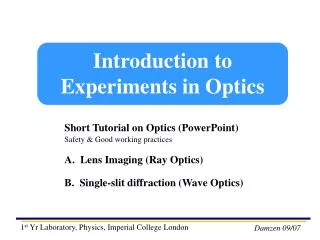
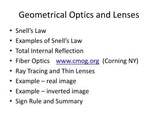
Lecture 2 – Geometrical Optics. b) Thin Lenses. Chapter 33 Lenses and Optical Instruments. Units of Chapter 33. Thin Lenses; Ray Tracing The Thin Lens Equation; Magnification Combinations of Lenses Lensmaker’s Equation. 33-1 Thin Lenses; Ray Tracing.

E N D
Lecture 2 – Geometrical Optics b) Thin Lenses
Units of Chapter 33 • Thin Lenses; Ray Tracing • The Thin Lens Equation; Magnification • Combinations of Lenses • Lensmaker’s Equation
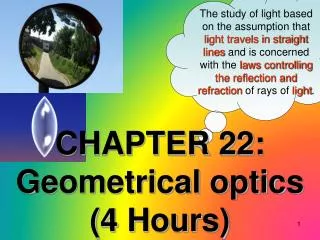
33-1 Thin Lenses; Ray Tracing Thin lenses are those whose thickness is small compared to their radius of curvature. They may be either converging (a) or diverging (b).
33-1 Thin Lenses; Ray Tracing Parallel rays are brought to a focus by a converging lens (one that is thicker in the center than it is at the edge).
33-1 Thin Lenses; Ray Tracing A diverging lens (thicker at the edge than in the center) makes parallel light diverge; the focal point is that point where the diverging rays would converge if projected back.
33-1 Thin Lenses; Ray Tracing The power of a lens is the inverse of its focal length: Lens power is measured in diopters, D: 1 D = 1 m-1.
33-1 Thin Lenses; Ray Tracing • Ray tracing for thin lenses is similar to that for mirrors. We have three key rays: • This ray comes in parallel to the axis and exits through the focal point. • This ray comes in through the focal point and exits parallel to the axis. • This ray goes through the center of the lens and is undeflected.
33-1 Thin Lenses; Ray Tracing Conceptual Example 33-1: Half-blocked lens. What happens to the image of an object if the top half of a lens is covered by a piece of cardboard?
33-1 Thin Lenses; Ray Tracing For a diverging lens, we can use the same three rays; the image is upright and virtual.
33-2 The Thin Lens Equation; Magnification The thin lens equation is similar to the mirror equation:
33-2 The Thin Lens Equation; Magnification • The sign conventions are slightly different: • The focal length is positive for converging lenses and negative for diverging. • The object distance is positive when the object is on the same side as the light entering the lens (not an issue except in compound systems); otherwise it is negative. • The image distance is positive if the image is on the opposite side from the light entering the lens; otherwise it is negative. • The height of the image is positive if the image is upright and negative otherwise.
33-2 The Thin Lens Equation; Magnification The magnification formula is also the same as that for a mirror: The power of a lens is positive if it is converging and negative if it is diverging.
33-2 The Thin Lens Equation; Magnification • Problem Solving: Thin Lenses • Draw a ray diagram. The image is located where the key rays intersect. • Solve for unknowns. • Follow the sign conventions. • Check that your answers are consistent with the ray diagram.
33-2 The Thin Lens Equation; Magnification Example 33-2: Image formed by converging lens. What are (a) the position, and (b) the size, of the image of a 7.6-cm-high leaf placed 1.00 m from a +50.0-mm-focal-length camera lens?
33-2 The Thin Lens Equation; Magnification Example 33-3: Object close to converging lens. An object is placed 10 cm from a 15-cm-focal-length converging lens. Determine the image position and size (a) analytically, and (b) using a ray diagram.
33-2 The Thin Lens Equation; Magnification Example 33-4: Diverging lens. Where must a small insect be placed if a 25-cm-focal-length diverging lens is to form a virtual image 20 cm from the lens, on the same side as the object?
33-3 Combinations of Lenses In lens combinations, the image formed by the first lens becomes the object for the second lens (this is where object distances may be negative). The total magnification is the product of the magnification of each lens.
33-3 Combinations of Lenses Example 33-5: A two-lens system. Two converging lenses, A and B, with focal lengths fA = 20.0 cm and fB = 25.0 cm, are placed 80.0 cm apart. An object is placed 60.0 cm in front of the first lens. Determine (a) the position, and (b) the magnification, of the final image formed by the combination of the two lenses.
33-4 Lensmaker’s Equation This useful equation relates the radii of curvature of the two lens surfaces, and the index of refraction, to the focal length:
33-4 Lensmaker’s Equation Example 33-7: Calculating f for a converging lens. A convex meniscus lens is made from glass with n = 1.50. The radius of curvature of the convex surface is 22.4 cm and that of the concave surface is 46.2 cm. (a) What is the focal length? (b) Where will the image be for an object 2.00 m away?
33-7 Magnifying Glass A magnifying glass (simple magnifier) is a converging lens. It allows us to focus on objects closer than the near point, so that they make a larger, and therefore clearer, image on the retina.
Summary of Chapter 33 • Lens uses refraction to form real or virtual image. • Converging lens: rays converge at focal point. • Diverging lens: rays appear to diverge from focal point. • Power is given in diopters (m-1):
Summary of Chapter 33 • Thin lens equation: • Magnification: