Download

1 / 24
260 likes | 550 Views
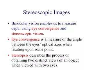
Stereoscopic Images. Stereopsis – Depth Perception. How do we perceive depth? Left and right eyes see slightly different images Images are forwarded to the brain Brain combines the two images. Image Construction . How does the Brain combine two images into one?

E N D
Stereopsis – Depth Perception • How do we perceive depth? • Left and right eyes see slightly different images • Images are forwarded to the brain • Brain combines the two images
Image Construction • How does the Brain combine two images into one? • Horizontal Disparity – the difference in horizontal position of a point in view between the two images • Brain implies depth based on this disparity – the greater the difference, the closer it must be. • Small disparity implies object is farther away
Problem • We can simulate this phenomenon in graphics by creating two images of the same scene and combining them to form one image. • But how do you represent the information from two separate images in one image?
Stereoscope • One of the first solutions • Each eye can only see one of the images • Brian combines them intoone image
Problem with Stereoscope • Awkward • Can’t translate well to other application such as movies • Must keep head still in a certain position
A better solution….. • Better to use only one actual image • What if we divided the information contained in a pixel into parts? • We could use one category of information strictly from the left image, and another category of information from the right image.
Share the Pixel!! • Color of a pixel – Red, Green, and Blue • Each pixel has a value for each • Use only the Red and Blue values for the left image, disregard the Green • Use only Green values for the right image, disregard the Red and Blue
Trioscopic 3D Image Right Image Left Image pixel pixel pixel Trioscopic Image
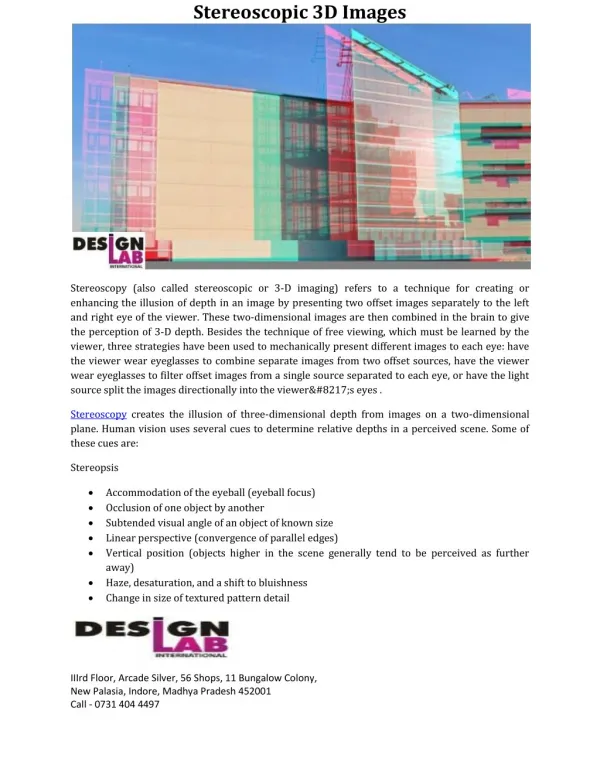
Light Filtering • Merge the two images so that the final image has all of its Red and Blue values only from the left image, and all of its Green values only from the right image. • Place colored cellophane filters over the eyes – one Magenta and the other Green. • The Green cellophane will filter out the green values so that the left eye only sees the Red and Blue values.
Light Filtering • Magenta cellophane filters out the Red and Blue values so that the right eye only sees the Green values. • This way, each eye sees a completely separate image • The Brain combines these images and infers depth based on Horizontal Disparity
Stereoscopy References • http://www.arachnoid.com/raytracing/anaglyphic_3d.html • http://en.wikipedia.org/wiki/Stereoscopy • http://en.wikipedia.org/wiki/RealD_Cinema • http://en.wikipedia.org/wiki/Circular_polarizer#Circular_Polarizers • http://en.wikipedia.org/wiki/Dolby_3D • http://en.wikipedia.org/wiki/Anaglyph_image#Possible_color_schemes • http://www.trioscopics.com/ • http://www.3dstereo.com/viewmaster/tri-gla.html
Traditional CG Camera Model • Pinhole Camera • All rays come from a single point • Perfect Focus – unrealistic
Depth of Field • The human eye has a limited depth of field • That area is “In Focus” • Other areas in the field of view appear sharper or fuzzier depending on their distance from the focal point along the viewing direction Camera Blur Blur Depth of Field
How do we simulate Depth of Field in Rendering? • Can create a blurring effect which is more or less severe depending on the distance from the focal point. • In Object-space (In-Rendering) • Distributed Ray Tracing aka stochastic ray tracing • In Image-space (Post-Rendering) • Per-pixel blur level control
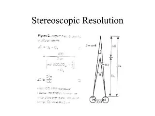
Distributed Ray Tracing • F – focal length • n – aperture number • C – circle of confusion • VP = FP/(P-F) • VD = FD/(D-F) • C = (|VD –VP|/VD) (F/n) • r = ½ (F/n) (D-P)/P • R = (-VP/D) r • R = ½ C
Per-pixel blur level control • Save the depth information for each pixel in the image. • Depth Map! • If a pixel needs blurring, average the pixels around it – using a greater number of neighbors the more it needs to be blurred • Gaussian blur
Depth of Field References • http://www.cs.berkeley.edu/~barsky/Blur/survey.pdf • http://delivery.acm.org/10.1145/810000/808590/p137-cook.pdf?key1=808590&key2=8080119921&coll=DL&dl=ACM&ip=69.91.175.135&CFID=10978387&CFTOKEN=86218611 • http://luthuli.cs.uiuc.edu/~daf/courses/ComputerGraphics/Week3/distributed-final.pdf • www.csie.ntu.edu.tw/~cyy/courses/rendering/05fall/assignments/pres/slides/DRT.ppt • http://en.wikipedia.org/wiki/Depth_of_field