Download
1 / 23
230 likes | 232 Views
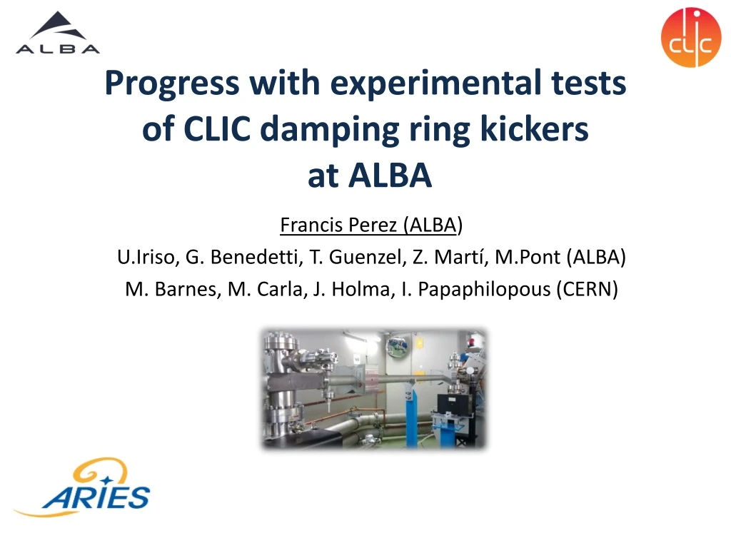
This article discusses the progress and experimental tests conducted on the CLIC damping ring kickers at ALBA synchrotron light source in Barcelona, Spain. The installation, characterization with beam, and measurement of transverse and longitudinal field homogeneity are explored. The results obtained demonstrate the precision and stability of the stripline kickers.

E N D
Progress with experimental tests of CLIC damping ring kickersat ALBA Francis Perez (ALBA) U.Iriso, G. Benedetti, T. Guenzel, Z. Martí,M.Pont (ALBA) M. Barnes, M. Carla, J. Holma, I. Papaphilopous(CERN)
2 • Introduction • Installation • StriplineCharacterizationwithBeam: • DC Kickusing HV PS • AC KickInductiveAdders • TransverseImpedanceMeasurements • Conclusions
IntroductiontoALBA –Synchrotron Light Source (in Barcelona, SPAIN)
IntroductiontoALBA –Synchrotron Light Source E = 3.0 GeV C = 268.8 m e = 4.0 nm·rad 8 BL x In operation BL29: BOREAS EU71– (0.08-3 keV) REsonantAbsorption and Scattering Bending:e-Diagnostics 4 BL x In construction BL01: MIRAS Bending– (0.4-100 µm) IR Spectroscopy BL24: CIRCE EU62– (0.1-2 keV) Photoemission spectroscopies BL04: MSPD SCW31 – (8-50 keV) HP/HR PowderDiffraction 100 MeV Linac 3 GeVBooster 3 GeV Storage Ring BLxx: FaxTor Wiggler Hard x-raytomography BL06: NOTOS Bending BL development BL22: CLÆSS MPW80– (2-63 keV) Absorption& EmissionSpectroscopies BL09: MISTRAL Bending– (0.27-2.6 keV) X rayMicroscopy BL11: NCD IVU21– (6-13 keV) Non CristallineDiffraction SAXS/WAXS BL20: LOREA EU150– (15-450 eV) ARPES BL13: XALOC IVU21 – (5-22 keV) MacromolecularCristallography BL12: XAIRA IVU21 – (5 – 22 keV) Microfocus
Introduction to the problem 5 • TheExtractionKickerat CLIC Damping Rings needs to provideverystablekicks to guaranteeLuminosity in a Bunch-by-Bunchcollisionrate • For thispurpose, a specialStriplineKickerwasdesigned[*] andmanufactured [**] withverystringentrequirements Beam pipe Feedthroughsforhighvoltage input/output Electrodes MACOR ring supports [*] C. Belver-Aguilar et al, Beam impedance study of the stripline kicker for the CLIC damping ring, Proc. IPAC 2012 [**] Vacuum Trinos S.L. , Valencia (Spain)
Introduction to the problem Requirements for the Extraction Kicker at CLIC Howthisprecision can be achievedandmeasuredwithinthisregion?? ALBA signedanagreementsignedwith CERN to characterizethestriplinewithbeamat ALBA Storage Ring
Installation in ALBA Storage Ring… E = 3.0 GeV C = 268.8 m e = 4.0 nm·rad 8 BL x In operation BL29: BOREAS EU71– (0.08-3 keV) REsonantAbsorption and Scattering Bending:e-Diagnostics 4 BL x In construction BL01: MIRAS Bending– (0.4-100 µm) IR Spectroscopy BL24: CIRCE EU62– (0.1-2 keV) Photoemission spectroscopies BL04: MSPD SCW31 – (8-50 keV) HP/HR PowderDiffraction 100 MeV Linac 3 GeVBooster 3 GeV Storage Ring BLxx: FaxTor Wiggler Hard x-raytomography BL06: NOTOS Bending BL development BL22: CLÆSS MPW80– (2-63 keV) Absorption& EmissionSpectroscopies BL09: MISTRAL Bending– (0.27-2.6 keV) X rayMicroscopy CLIC Stripline BL11: NCD IVU21– (6-13 keV) Non CristallineDiffraction SAXS/WAXS BL20: LOREA EU150– (15-450 eV) ARPES BL13: XALOC IVU21 – (5-22 keV) MacromolecularCristallography BL12: XAIRA IVU21 – (5 – 22 keV) Microfocus
…maintaining ALBA Operation 24/24h 7/7days AverageAvailability in the last 5 years = 97,5%
Installation Besides the stripline, the beam characterization required also to design & install 2 additional BPMs, absorbers and transition chambers , vacuum pumps… OLDBPM BPM08-01 NEW BPM BPM07-10 NEW BPM BPM07-09 OLDBPM BPM07-08 Striplinechamber SR_08 Absorber Downstreamtaperedchamber SR_07 Upstreamstraightchamber e-beam
Installation To avoid vacuum conditioning problems,it was decided to install & uninstall every time to test the stripline with (low current) beams
Stripline Characterization with Beam Sep. 2018 (installedduring 4 days) Transverse Field Homogenety – DC HVPS TransverseBeamCouplingImpedance Jan. 2019 (installedduring5 days) Longitudinal Pulse Homogeneity (InductiveAdder) Longitudinal BeamCouplingImpedance (incomplete)
StriplineTransverse Field Homogeneity • Measurements with the HV DC power supplies: • Commissioning: stripline sparked a lot with beam, and it took ~2days to reach +/-10kV and 13mA beam! • Local Angle Measurement using 4 BPMs HVPS OFF HVPS ON
StriplineTransverse Field Homogeneity BPM Calibration (Stripline off) Measurement precision improved if BPM precision improves With the stripline off, the position along 4 consecutive BPMs should follow a straight line. We did bumps along +/1mm, and used the data to fit the BPMs offsets, gains, & rolls that minimize the discrepancies BPM0708 BPM0709 corrected BPM0710 BPM0801
StriplineTransverse Field Homogeneity Measurements (Stripline on @10kV) around ±(1,1)mm HVPS OFF HVPS ON Z. Martí Effective kick at ±10kV: 544.4±0.2 µrad (theoretically, 560 urad) -Homogeneity of 3.7·10-4 ±5.3·10-4(compatible with CLIC requirements <2·10-4)
Longitudinal pulsedfieldhomogeneity Measurements:Field flat-top stability and pulse-pulse repeatability 160-900ns Beam/Magnetickick 20ps/2ns 896ns time • Measurements in single bunch: scan the pulse-bunch delay along the pulse flat-top • Vary pulse width (160 – 900)ns and delay • Use global amplitude with all 120 BPMs, TBT data (500 turns), and with enough averaging (50 shots) to reach required precision (1e-4)
Longitudinal pulsedfieldhomogeneity Lab Tests and Installation @ALBA • HV (10kV) pulse of length [160 – 900]ns performed with Inductive Adders • Long cables might distort the pulse. To avoid it, the inductive adders were installed inside the ALBA tunnel • Both the stripline and Inductive Adders were removed after the tests J. Holma Stripline Inductive Adders
Longitudinal pulsedfieldhomogeneity Measurements with Beam InductiveAddersable to produceanoverpulsewithslowdecay[*], so thatthebeam can see a flat kick (flat total combination of electric and magnetic fields – see [**]) Reachedhomogeneity of +/-0.02% Flat-top pulse DecaySignalpulse Beam Signal ControlledDecay ByInductiveAdders IA off IA off [*] J. Holma, The Prototype Inductive Adder With Droop Compensation for the CLIC Kicker Systems, IEEE Transaction of Plasma Science, Oct. 2014 [**] C. Belver-Aguilar, "Transient Studies of the Stripline Kicker for Beam Extraction from CLIC Damping Rings", in Proc. IBIC'16, Barcelona, Spain (2016)
Longitudinal pulsedfieldhomogeneity Measurements with Beam Z. Martí and J. Holma The strip-line kick at 2x5kV with a 160ns flat-top is measured with different timing delays. The pulser unit compensation works as expected and pulse correction droop was successfully tested
Longitudinal fieldhomogeneity Measurements with Beam • Longitudinal fiel homogeneity results: • Single Meas: 0.01% • Average Variation: 0.04%
Transverse Impedance Measurement Strategy 1: Measuring the transverse impedance of the total ring before and after the installation of the striplines. Single bunch measurements to determine TMCI threshold and detuning slope. (Data taken at ξV=0 and different Vrf). Example of TMCI measurement Summary with vs w.o. CLIC SL T. Guenzel Very noisy, probably due to machine repeatibility. But consistent with expectations: Measured Impedance: (bZ)eff= 11.6 kW From Gdfidl simulations: (bZ)eff = 11 +/- 12 kW
Transverse Impedance Measurement Strategy 2: Local Bump • Produce a vertical bump of y0 at the SL location (+/-1mm) • Get orbit at high beam current, IH (8 mA/bunch, limited by beam instabilities) • Scrape down the beam until a “low” beam current is reached IL (min of 1mA/bunch) • Get orbit at low beam current • The difference between the orbits at 2) and 4) is due to the impedance of the SL Measured Impedance Kick: 0.033±0.017 µrad/mm/mA Kick from Gdfidl simulations: 0.0244 µrad/mm/mA
SUMMARY & CONCLUSIONS Beam characterization has been done by installing the Stripline several times Although this limited the time for experiments, a full characterization has been carried out: • Vacuum Conditioning: could not reach beam currents >140mAw.o. compromising machine operation (within the scheduled time ) • Transverse Field Homogeneity – HV DC tests • Longitudinal Field Homogeneity – Inductive Adder • Transverse Beam Coupling Impedance