Download
1 / 142
1.42k likes | 1.5k Views
Explore the essential features and architecture of 8051 microcontrollers, including addressing modes and instruction set. Learn about the criteria for choosing a microcontroller efficiently and cost-effectively.

E N D
UNIT V – Microcontroller • 8051 – Introduction, Architecture, Addressing Modes and Instruction Set
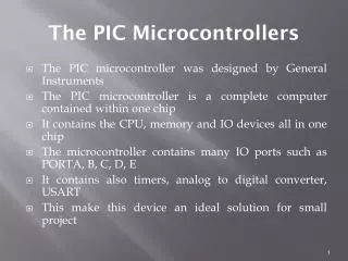
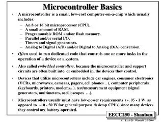
INTRODUCTION Three criteria in Choosing a Microcontroller • meeting the computing needs of the task efficiently and cost effectively • speed, the amount of ROM and RAM, the number of I/O ports and timers, size, packaging, power consumption • easy to upgrade • cost per unit • availability of software development tools • assemblers, debuggers, C compilers, emulator, simulator, technical support • wide availability and reliable sources of the microcontrollers.
INTRODUCTION • a Harvard architecture (separate instruction/data memories) • single chip microcontroller (µC) • developed by Intel in 1980 for use in embedded systems. • today largely superseded by a vast range of faster and/or functionally enhanced 8051-compatible devices manufactured by more than 20 independent manufacturers
INTRODUCTION Comparison of the 8051 Family Members Feature8051 8052 8031 ROM (program space in bytes) 4K 8K 0K RAM (bytes) 128 256 128 Timers 2 3 2 I/O pins 32 32 32 Serial port 1 1 1 Interrupt sources 6 8 6
8051 microcontroller features • 12 MHz clock. Processor instruction cycle time 1 µs. [in Classic version] • An 8-bit ALU. • Harvard memory architecture – the external program memory and data memory have separate address spaces from 0x0000 and separate control signal(s). • 8-bit internal data bus width and 16-bit internal address bus – Harvard memory architecture • CISC (Complex Instruction Set Computer)
8051 microcontroller features (contd.) • Special function registers (SFRs) –PSW (processor status word), A (accumulator), B register, SP (stack pointer) and registers for serial IOs, timers, ports and interrupt handler. • Special bit manipulation instructions. • 16-bit Program counter with initial default reset value defined by processor is 0x0000. • 8-bit stack pointer with initial default value defined by processor is 0x07
8051 microcontroller features (contd.) • Classic 8051 simple architecture • no floating-point processor, • no cache, • no memory management-unit, • no atomic operations unit, • no pipeline and • no instruction level parallelism
8051 microcontroller features (contd.) • on-chip RAM of 128 bytes. [8052-version RAM 256 bytes.] • 32 bytes of RAM also used as four banks (sets) of registers. Each register-set (bank) thus eight registers. • External data/stack memory can be added upto 64 kB in most version. In certain 8051 enhancements, this limit enhanced to 16 MB
Vcc P1.0 1 40 P0.0(AD0) P1.1 2 39 P0.1(AD1) P1.2 3 38 P0.2(AD2) P1.3 4 37 8051 (8031) P0.3(AD3) P1.4 5 36 P0.4(AD4) P1.5 6 35 P0.5(AD5) P1.6 7 34 P0.6(AD6) P1.7 8 33 P0.7(AD7) RST 9 32 (RXD)P3.0 EA/VPP 10 31 (TXD)P3.1 ALE/PROG 11 30 PSEN (INT0)P3.2 12 29 P2.7(A15) 13 28 (INT1)P3.3 (T0)P3.4 P2.6(A14) 14 27 (T1)P3.5 P2.5(A13) 15 26 P2.4(A12) (WR)P3.6 16 25 P2.3(A11) (RD)P3.7 17 24 P2.2(A10) XTAL2 18 23 P2.1(A9) XTAL1 19 22 P2.0(A8) GND 20 21 PIN DESCRIPTION OF 8051
Pins of 8051 • Vcc(pin 40): • Vcc provides supply voltage to the chip. • The voltage source is +5V. • GND(pin 20):ground • XTAL1 and XTAL2(pins 19,18): • These 2 pins provide external clock. • Way 1:using a quartz crystal oscillator • Way 2:using a TTL oscillator • Example 4-1 shows the relationship between XTAL and the machine cycle.
Pins of 8051 • RST(pin 9):reset • It is an input pin and is active high(normally low). • The high pulse must be high at least 2 machine cycles. • It is a power-on reset. • Upon applying a high pulse to RST, the microcontroller will reset and all values in registers will be lost. • Reset values of some 8051 registers • Way 1:Power-on reset circuit • Way 2:Power-on reset with debounce
Pins of 8051 • /EA(pin 31):external access • There is no on-chip ROM in 8031 and 8032 . • The /EA pin is connected to GND to indicate the code is stored externally. • /PSEN & ALE are used for external ROM. • For 8051, /EA pin is connected to Vcc. • “/” means active low. • /PSEN(pin 29):program store enable • This is an output pin and is connected to the OE pin of the ROM.
Pins of 8051 • ALE(pin 30):address latch enable • It is an output pin and is active high. • 8051 port 0 provides both address and data. • The ALE pin is used for de-multiplexing the address and data by connecting to the G pin of the 74LS373 latch. • I/O port pins • The four ports P0, P1, P2, and P3. • Each port uses 8 pins. • All I/O pins are bi-directional.
Pins of 8051 • Using a quartz crystal oscillator • We can observe the frequency on the XTAL2 pin. • The 8051 has four I/O ports • Port 0 (pins 32-39):P0(P0.0~P0.7) • Port 1(pins 1-8):P1(P1.0~P1.7) • Port 2(pins 21-28):P2(P2.0~P2.7) • Port 3(pins 10-17):P3(P3.0~P3.7) • Each port has 8 pins.
Pins of 8051 • Named P0.X (X=0,1,...,7), P1.X, P2.X, P3.X • Ex:P0.0 is the bit 0(LSB)of P0 • Ex:P0.7 is the bit 7(MSB)of P0 • These 8 bits form a byte. • Each port can be used as input or output (bi-direction).
Data Transfer Instructions • Move byte between accumulator (an SFR) and register at a register bank • Move byte from an SFR/Internal RAM to another direct • Move indirect • Move immediate, MOV immediate DPTR • MOVC and MOVX indirect • Exchange or Push or Pop direct
Bit and Byte Manipulations and Logic instructions Bit Manipulation • Set, Complement, AND or OR or MOV the bit Logic Instructions • AND, XOR, OR Operation Instructions Byte Manipulation • Clear, complement, rotate instructions
Arithmetic Instructions • 8-bit Add, Subtract, Multiply and divide Instructions • Increment-Decrement Instructions
Program Flow Control Instructions • Branch instructions • Conditional jumps • Decrement and Jump conditional • Compare and then conditional jump • Subroutine Call Instructions • NOP • Delay
Interrupt Flow Control Instructions • Interrupt flow control- mask bits, priority bits • RETI
Addressing Modes • Addressing modes specifies where the data (operand) is. They specify the source or destination of data (operand) in several different ways, depending upon the situation. • Addressing modes are used to know where the operand located is.
Addressing Modes • There are 5 types of addressing modes: • Register addressing. • Direct addressing. • Register indirect addressing. • Immediate addressing. • Index addressing.
Register Addressing Mode • In register addressing mode; the source and/or destination is a register. • In this case; data is placed in any of the 8 registers(R0-R7); in instructions it is specified with letter Rn (where N indicates 0 to 7).
Register Addressing Mode • For example; • ADD A, Rn (This is general instruction). • ADD A, R5 (This instruction will add the contents of register R5 with the accumulator contents).
Direct Addressing Mode • In direct addressing mode; the address of memory location containing data to be read is specified in instruction. • In this case; address of the data is given with the instruction itself.
Direct Addressing Mode • For example; • MOV A, 25H (This instruction will read/move the data from internal RAM address 25H and store it in the accumulator.
Register Indirect Addressing Mode • In register indirect addressing mode; the contents of the designated register are used as a pointer to memory. • In this case; data is placed in memory, but address of memory location is not given directly with instruction.
Register Indirect Addressing Mode • For example; • MOV A,@R0 This instruction moves the data from the register whose address is in the R0 register into the accumulator.
Immediate Addressing Mode • In immediate addressing mode, the data is given with the instruction itself. • In this case; the data to be stored in memory immediately follows the opcode.
Immediate Addressing Mode • For example; • MOV A, #25H (This instruction will move the data 25H to accumulator.
Index Addressing Mode • Offset (from accumulator) is added to the base index register( DPTR OR Program Counter) to form the effective address of the memory location. • In this case; this mode is made for reading tables in the program memory.
Index Addressing Mode • For example; • MOVC A, @ A + DPTR ( This instruction moves the data from the memory to accumulator; whose address is computed by adding the contents of accumulator and DPTR)
UNIT V – Microcontroller • Timers/Counters – Serial communication – Assembly Language Program – Applications of Microcontroller. PREPARED BY GAYATHR.M ASSISTANT PROFESSOR DEPARTMENT OF COMPUTER SCIENCE AND ENGINEERING SRM UNIVERSITY
Timers /Counters Programming • The 8051 has 2 timers/counters: timer/counter 0 and timer/counter 1. They can be used as • The timer is used as a time delay generator. • The clock source is the internal crystal frequency of the 8051. • An event counter. • External input from input pin to count the number of events on registers. • These clock pulses cold represent the number of people passing through an entrance, or the number of wheel rotations, or any other event that can be converted to pulses.
Timer • Set the initial value of registers • Start the timer and then the 8051 counts up. • Input from internal system clock (machine cycle) • When the registers equal to 0 and the 8051 sets a bit to denote time out 8051 P2 P1 to LCD Set Timer 0 TH0 TL0
Counter • Count the number of events • Show the number of events on registers • External input from T0 input pin (P3.4) for Counter 0 • External input from T1 input pin (P3.5) for Counter 1 • External input from Tx input pin. • We use Tx to denote T0 or T1. 8051 TH0 P1 to LCD TL0 P3.4 T0 a switch
Registers Used in Timer/Counter • TH0, TL0, TH1, TL1 • TMOD (Timer mode register) • TCON (Timer control register) • Since 8052 has 3 timers/counters, the formats of these control registers are different. • T2CON (Timer 2 control register), TH2 and TL2 used for 8052 only.
Basic Registers of the Timer • Both timer 0 and timer 1 are 16 bits wide. • These registers stores • the time delay as a timer • the number of events as a counter • Timer 0: TH0 & TL0 • Timer 0 high byte, timer 0 low byte • Timer 1: TH1 & TL1 • Timer 1 high byte, timer 1 low byte • Each 16-bit timer can be accessed as two separate registers of low byte and high byte.
TH0 TH1 TL0 TL1 D15 D15 D14 D14 D13 D13 D12 D12 D11 D11 D10 D10 D9 D9 D8 D8 D7 D7 D6 D6 D5 D5 D4 D4 D3 D3 D2 D2 D1 D1 D0 D0 Timer Registers Timer 0 Timer 1
(MSB) (LSB) GATE C/T M1 M0 GATE C/T M1 M0 Timer 1 Timer 0 TMOD Register • Timer mode register: TMOD MOV TMOD,#21H • An 8-bit register • Set the usage mode for two timers • Set lower 4 bits for Timer 0 (Set to 0000 if not used) • Set upper 4 bits for Timer 1 (Set to 0000 if not used) • Not bit-addressable
(MSB) (LSB) GATE C/T M1 M0 GATE C/T M1 M0 Timer 1 Timer 0 Figure 9-3. TMOD Register GATE Gating control when set. Timer/counter is enabled only while the INTx pin is high and the TRx control pin is set. When cleared, the timer is enabled whenever the TRx control bit is set. C/T Timer or counter selected cleared for timer operation (input from internal system clock). Set for counter operation (input from Tx input pin). M1 Mode bit 1 M0 Mode bit 0
C/T (Clock/Timer) • This bit is used to decide whether the timer is used as a delay generator or an event counter. • C/T = 0 : timer • C/T = 1 : counter
Gate • Every timer has a mean of starting and stopping. • GATE=0 • Internal control • The start and stop of the timer are controlled by way of software. • Set/clear the TR for start/stop timer. • GATE=1 • External control • The hardware way of starting and stopping the timer by software and an external source. • Timer/counter is enabled only while the INT pin is high and the TR control pin is set (TR).
M1, M0 • M0 and M1 select the timer mode for timers 0 & 1. M1 M0 Mode Operating Mode 0 0 013-bit timer mode 8-bit THx + 5-bit TLx (x= 0 or 1) 0 1 116-bit timer mode 8-bit THx + 8-bit TLx 1 0 28-bit auto reload 8-bit auto reload timer/counter; THx holds a value which is to be reloaded into TLx each time it overflows. 1 1 3 Split timer mode
Example 9-3 Find the value for TMOD if we want to program timer 0 in mode 2, use 8051 XTAL for the clock source, and use instructions to start and stop the timer. Solution: TMOD= 00000010 Timer 1 is not used. Timer 0, mode 2, C/T = 0 to use XTAL clock source (timer) gate = 0 to use internal (software) start and stop method. timer 1timer 0