Download
1 / 33
330 likes | 430 Views
Where we are with lasers performance for polarized e + sources ? KEK, Junji Urakawa. From two-mirror cavity to four-mirror cavity under International collaboration with LAL. laser beam. e- beam. 0.11 mJ / pulse, waist = 30 m, 357MHz. 1. Constraints for polarized e+ source

E N D
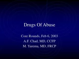
Where we are with lasers performance for polarized e+ sources ? KEK, Junji Urakawa From two-mirror cavity to four-mirror cavity under International collaboration with LAL. laser beam e- beam 0.11 mJ / pulse, waist = 30 m, 357MHz 1. Constraints for polarized e+ source 2. Short review of pulsed laser stacking 3. Burst Laser Amplification 4. Mirror damage which is caused by peak power density and average power density on the mirror. 5. Summary 50 mJ / pulse, waist = 10 m, 178.5MHz IWLC2010
Polarised positron source: ILC baseline solution, the undulator scheme Requires ~200m of SC helicoidal undulator6mm diameter beam pipe IWLC2010
Alternative solution Compton polarised positron source for the ILC Araki et al. arXiv:physics/0509016 The e+ are longitudinally polarised • Experimental proof at ATF • Omori et al.PRL 96(2006)114801 S Compton Omori-san’s picture E Compton(GeV) IWLC2010 I. Applications/Source e+
Compton Ring • Inverse Compton scattering between electron stored in a ring (CR) and laser light stored in optical cavities. • Energy spread of the electron beam is increased by the scattering. 10 ms interval for the beam cooling. • 100 times stacking in a same bucket of DR makes the required bunch intensity. IWLC2010 Kuriki; POSIPOL2010
CLIC Compton Scheme • It is based on CR scheme. • Due to the less bunch intensity, it is slightly easier than that for ILC. • Pre-Damping ring is used as positron accumulator (stacking). IWLC2010 Kuriki: POSIPOL2010
ERL scheme • Electron is provided by ERL (Energy Recovery Linac). • Both advantages (high yield at Linac and high repetition at CR) are compatible in the ERL solution. • Continuous stacking of e+ bunches on a same bucket in DR during 100ms, the final intensity is 2E+10 e+. • Another 100ms is used for damping. IWLC2010 Kuriki: POSIPOL2010
to e+ conv. target 4GeV 1A e- beam 30MeV beam 15MeV e+ beam ~2 m Linac Scheme • CO2 laser beam and 4 GeV e-beam produced by linac. • 4GeV 15nC e- beam with 12 ns spacing. • 10 CPs, which stores 10 J CO2 laser pulse repeated by 83 MHz cycle. • 5E+11 γ-ray -> 2E+10 e+ (2% conversion) • 1.2μs pulse, which contains 100 bunches, are repeated by 150 Hz to generate 3000 bunches within 200ms. • Laser system relies on the commercially available lasers but need R&D for high repetition operation. • Ring cavity with laser amplifier realizes the CO2 laser pulse train. By V. Yakimenko IWLC2010
Main drawback of Compton scattering: the flux Compton/Thomson cross sectionsTis very small To reach high photon fluxes: 2 main technical issues High laser power Typically >1MW average power !Small laser beam waist Typically tens of microns or less All that forpicosecond laser beamBest e_bunch length ~1ps • Ie: electron beam intensity • PL: laser power • : laser beam wavelength a: crossing angle selectron=electron beam size r.m.s slaser=laser beam size r.m.s IWLC2010
Techniques to increase the flux 9 KEK and LAL choice Tokyo University Compton machine Single-collision scheme Multi-collision scheme IWLC2010
Single-Collision schemes 10 TeraWatt, but low rep rate …(e.g. Chingua Univ.& Daresbury project) Non linear cavity (LLNL) Jovanovic et al.,NIMA578(2007)160 Regenerative cavity Sprangle et al. JAP72(1992)5032 Fabry-Perot cavity Huang&Ruth, PRL 80(1998)976 • Mode lock laser beam can be stabilisedto Fabry-Perot cavities: • Jones et al., Opt.Comm.175(2000)409, Jones et al., PRA69(2004)051803(R) • A priori no limitation from dispersion induced by mirror coatings in picosecond regime: • Petersen&Luiten,OE11(2003)2975,Thorpe at al., OE13(2005)882 IWLC2010
1. Constraints for polarized e+ source Laser pulse width : a few psec〜30psec (FWHM) Closing angle <10 deg. Laser rep. rate : 50MHz〜500MHz Laser energy for cavity injection: 50W〜500W Optical cavity gain : 1000〜10000 Laser size<10mm IWLC2010
The laser amplification R&D We use Ytterbium dopedphotonic crystal fiber as amplifier • We obtained 200W but spot was not stable • We fix the power to ~50W to get stable laser beam • Thermal control issues to be solved before increasing power • Also damage protection issues are not easy to solve at very high power (we broke many fibers…) • Recent publication shows 800W average power (11µJ/pulse)with same techniques (Limpert,OL35(2010)94) • but we need long term stability and reliability… • technological R&D Ø core = 40 µm Ø cladding = 200 µm Towardcavity laser Fiberamplifier IWLC2010
2. Short review of pulsed laser stacking Continuous laser beam 1. JLab (CEBAF/polarimeter – gain ~104 Falleto et al. (NIMA459(2001)412) 2. HERA/polarimeter – gain ~104 3. KEK-ATF/laser wire – gain ~1000, waist ~5mm Pulsed laser beam 1. ~ 30ps pulses & gain ~6000, waist ~60mm (Lyncean Tech.) 2. 7ps @357MHz (Compton x-ray generation), R&D in progress Total gain ~12000 with burst mode (cavity gain ~600), waist ~30mm (KEK-ATF), average power =40kW 3. At LAL we locked ps Ti:sapph oscillator to 10000 gain cavity (but few seconds…) 4. Garching (in 2010), gain=1800, Power_inside = 72kW IWLC2010
Considering two-mirror cavity, reflectance R, transmissivity T, and losses L where R+T+L = 1 by energy conservation. The “bounce number” b which is defined from the round-trip power loss in a cavity, ∝ e−1/b.FSR : free spectral range If R=R1=R2 IWLC2010
Perfect resonance : L = L laser cavity Imperfect Resonance : L ~ L laser cavity Not resonance : L ≠ L laser cavity Storage of laser pulse Resonance condition : The relationship with laser and cavity : The enhancement factor is the function of reflectivity, Δl and laser pulse width. IWLC2010
Achievement on related technique JFY2003 CW Laser wire beam size monitor in DR 14.7µm laser wire for X scan 5.7µm for Y scan (whole scan: 15min for X, 6min for Y) 300mW 532nm Solid-state Laser fed into optical cavity IWLC2010
Laser wire block diagram Free spectral range :532nm/2=266nm Line width=0.3nm optical cavity resonance is kept by piezo actuator IWLC2010
Experimental results(Pulse Laser Storage) Laser: Mode Lock: Passive SESAM Frequency: 357MHz Cavity length: 0.42 m Pulse width: 7.3 p sec (FWHM) Wave Length: 1064 nm Power: ~ 6W SESAM: SEmi-conductor Saturable Absorber Mirrors IWLC2010
Ext. Cavity: Cavity: Super Invar Cavity length: 420mm Mirrors: Reflectivity: 99.9%, 99.9% (maybe, 99.98%) Curvature: 250 mm (s0 = 90μm) super invar 62φ IWLC2010
・Finesse: R = 99.98% Finesse =πτc/l τ:decay time c: light verocity l: cavity length PD PBS PBS P.C. Trans. τ~ 3.0μsec F ~ 6300 JFY 2004 IWLC2010
Laser Undulator Compact X-ray (LUCX)Project at KEK-ATF Multi-bunch photo-cathode RF Gun 43MeV Multi-bunch beam+ Super-Cavity = 33keV X-ray. X-ray Detector S-band Acc. Structure Beam size at CP 60mm in s Multi-bunch e- beam 300nC at gun At present, laser waist size is 30mm in s. We should reduce both beam size at CP down to 30mm. 33keV X-ray generation based on inverse Compton scattering was started from May 2007 with Super-Cavity. Storage Laser power 40kW, 7psec(FWHM), next step :1MW IWLC2010
3. Burst Laser Amplification Laser Diode Amplification by 500 Operation test was done. IWLC2010 IWLC2010 22
IWLC2010 IWLC2010 24
IWLC2010 IWLC2010 25
IWLC2010 IWLC2010 26
4. Mirror damage which is caused by peak power density on the mirror. Storage average power 40kW or more (maybe 120kW) Laser size on mirror 440 mm Then, reduce waist size from 160 mm to 60 mm. Laser size on mirror 1174 mm damaged coating size ~100 mm Depth (p-p) 5.5 mm Waist size in sigma from 80 mm to 30 mm Good coating spherical mirror damage threshold : Average power density on mirror ~10 MW/cm2 Peak power density on mirror ~10 GW/cm2 IWLC2010
REO and SOC mirror threshold are a little small : 6.7 GW/cm2 and 1.6 GW/cm2 We designed asymmetric reflective mirror configuration to increase the coupling : 99.7% and 99.9% . Then, we found damaged mirror was low reflective one. When we introduced burst mode operation for x-ray generation with F.L. pumped amplifier, we might increase average power in the cavity until 120kW. It means ~20GW/cm2. Now we keep 40kW average power with larger beam size 1174 mm on the mirror ,which corresponds 0.8GW/cm2. Maybe, burst mode operation is interesting, I show several slides for this. IWLC2010
Four-mirror Fabry-Perot cavity R&D at ATF French Japanese Collaboration N. Delerue] IWLC2010 29 Araki-san
2 steps R&D ATF 2-mirror cavity paper: Miyoshi, arXiv:1002.3462v1 Started end 2008 STEP ONE: commissioning a 4-mirror cavity at ATF by end 2010 STEP TWO: upgrade mirrors & laser power ~50W 200W Oscillator =0.2W, 1032nm Dt~0.5ps frep=178.5MHz Amplifier photonic fiberYb Doped 4-mirror Fabry-Perot cavity Gain~1000 10000 Digital feedback ATF clock STEP ONE With cavity laser/coupling ~50% Power_cavity~25kW ~50x1.5 vs 2-mirror cavity~5 E9 g/s (Emax=28MeV) STEP TWO With cavity laser/coupling ~50% Power_cavity~500kW ~2000x1.5 vs 2-mirror cavity~2 E11g/s Goal: to reach the MW average power IWLC2010 30
12 deg. IWLC2010 IWLC2010 31 IWLC2010 31
5. Summary • Establish feedback system to keep the resonance • condition precisely. • 2. 4-mirror ring cavity has a good tolerance to achieve • gain near 104 and waist size 10 mm or less in sigma. • 3. Take care of the mirror damage and need safety margin. Proposal: Systematic Mirror Damage Experiment to JSPS. If approve, start this experiment from April next year. IWLC2010
Summary 33 • Compton scattering is a very useful process • But X-section is smallhuge laser power requiredR&D • There is now a new 4-mirror fabry-perot cavities in ATF to contribute to this R&D effort 2-mirror cavitypulsed laser 4-mirror cavity pulsed laser 2X 2-mirror cavitiescw laser(laser-wire) The new cavity has 4 mirrors and is non-planar to match requests of futur Compton e+ polarised sources or compact X-ray machines IWLC2010