Download
1 / 25
250 likes | 411 Views
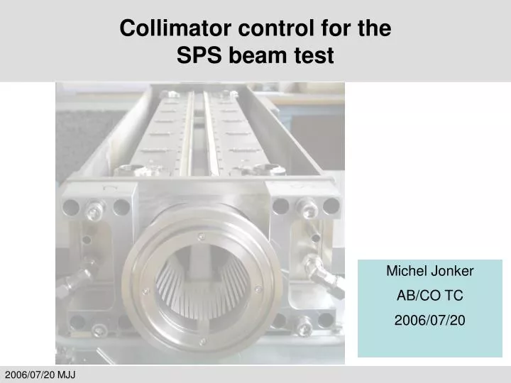
Collimator control for the SPS beam test. Michel Jonker AB/CO TC 2006/07/20. Dates of the SPS beam tests. Dedicated SPS MD to test the LHC collimators in TT40 (1 x 16 h. extracted beam, collimator robustness test) LSS5 (2 x 24h. circulating beam, test of collimation principles & physics)

E N D
Collimator control for theSPS beam test Michel Jonker AB/CO TC 2006/07/20
Dates of the SPS beam tests Dedicated SPS MD to test the LHC collimators in • TT40 (1 x 16 h. extracted beam, collimator robustness test) • LSS5 (2 x 24h. circulating beam, test of collimation principles & physics) Schedule • W40 TT40 (October 2…) • W42 LSS5 (October 16…) • W44 LSS5 (October 30…) • W46 reserve (November 13…) Note: Commissioning of collimators installed in transfer line and LHC Sector 8-1 Electronics available? (one moveable rack?)
Objectives of the SPS beam tests TT40 (extracted beam: 6 shots of 3.3 1013, W40) • Test with laser vibrometer • Damage tests. (Note test of new jaw design following result of 2004 damage tests) • BCT transmission to test alignment of collimators? LSS5(circulating beam W42 & W44) • Commissioning of controls, test of sensors, etc. • Collimator calibration(Beam based alignment, LHC BLM’s & electronics) • Impedance measurement (Measure inductive bypass effect) • Halo studies(Tail repopulation studies, LHC BLM’s & electronics) • High current related measurements(Temperature, EM noise signals, cooling…) • Beam loss maps(SPS BLM, recorded at a rate > 1 Hz) • Vacuum pressure measurements ? Detailed program will be worked out by collimation working group after holiday period.
Collimator Hardware 3rd TCS CERN prototype Collimator Upper plug-in Lower plug-in Base support
Collimator Hardware Side view at one end Vacuum tank Movement for spare surface mechanism (1 motor, 2 switches, 1 LVDT) CFC CFC Temperature sensors Microphone Reference Reference Motor Motor Sliding table Gap opening (LVDT) Resolver Resolver Gap position (LVDT) + switches for IN, OUT, ANTI-COLLISION
Collimator Hardware Motor Control Power Drive control RS485 Stepper Controller Motor PowerDrive M Step Up/Down Fault 2 phases Trigger Motors: Ordered Motor Power Drive: Tender sent out, result half September Stepper Controller: Technology study finished, our choice to be approved
Collimator Hardware Position Sensors E1 ~ E2 E1 - E2Ep ~ LVDT electronics Sine waveGenerator Sine waveGenerator . Df T D V L Processor ADC FRONT-END ADC PROFIBUS PLC ADC DAC P m ADC LVDT Special “Conditioner” Electronics required to filter noise from the signal (sample over a few cycles) i.e. output cannot be plugged into a regular PLC (= slow) ADC module More complications with individual coil readout… Resolver
Collimator Control for the LHC • Architecture • Milestones • Where we stand today (in preparation of the SPS tests): • low level • Options: PLC / VME / PXI • `recommendations • collimator supervisor • control room applications • link with BLM system • For follow up • Conclusions
LHC Collimator Control Architecture • Control room software: • Management of settings (LSA) • Preparation for ramp • Assistance in collimator tuning • Based on standard LSA components • Dedicated graphical interface for collimator control and tuning • Collimator supervisor: • Fesa Gateway to Control Room Software • Synchronization of movements • Beam Based Alignment • Support building, VME • Takes action on position errors (FB) • Receives timing, send sync signals over fiber to low level (ramp & Alignment) • Environmental Supervision • Communication with BLM using UDP • Low level control systems • Motor drive • Position readout and survey • Environment Survey • Down stairs, PLC/VME/PXI? • 3 distinct systems / combined?
Collimator Control Milestones • August 2006:Basic command-driven control of single collimators for SPS test, TT40 test and commissioning of transfer line collimators. • March 2007: First tests on function-driven, synchronized control of a collimator ensemble (several 10's of collimators), like required for the LHC. • August 2007: Controls for collimator beam-based calibration. Function-driven, synchronized control for the LHC collimation system for commissioning (no automatic BLM-based setup). • March 2008: First tests on automatic BLM-based collimator set-up. • July 2008:Availability of fast automatic BLM-based collimator set-up to allow for efficient machine set-up for luminosity of up to 1033 (up to 30% of nominal beam intensity).
Low level control Study by A.Masi (+ A.Brielmann, M.Donze) Requirements driving the choice for the low level system: • Reliability (collimators protect the machine) • Limited rack space (19” x 12U x 400 mm deep rack should house controls for two collimators • The jaws positioning a few μ resolution, 20 μreproducibility • Two modes of operation: • Move a jaw by a predefined number of steps, with start synchronized by a (repeatable) digital trigger from CSS (Beam based alignment). • Download in the low level equipment a function (position-time table). Then all jaws will start after receiving the digital trigger (about 400 motors) • Possibility to download a new function while the previous is running
Low level control Trigger delay Stop jitter Start jitter Profile duration Requirements driving the choice for the low level system (cont) BLM based setup Ramp Trigger delay: <1ms <100ms Start jitter: <1ms <10ms (<1ms on the same jaw!) Stop jitter: <10ms (after 15 minutes) Note: 10 ms error @ 1mm/s => 10 μ error Acquire LVDT and resolvers within a 20ms cycle, 10 ms if possible, check in real time that the actual position is within a given limit function (synchronized with function execution).
low level control 1a. Siemens PLC: CPU S7300, + 1 x FM 357-2:4-axis controller 1b. Siemens PLC:CPU 317, 4 x FM 353:1 axis controller 2. VME crate Power PC RIO 3 3. PXI system National Instruments • Controller Pentium IV 2.0 Ghz 1 Gb RAM, LabView RT • 7833R FPGA 3M gates card that hosts the control for 10 stepping motor axis • DAQ card 6289 18 bit multiplexed with 16 diff analog input to acquire the output signals of 7 LVDT • Timing Card 6608 with 45 ppb clock stability-8 Timers for resolver reading • CAN BUS card
is very well supported by IT/CO 3–Performances-Costs Comparison
low level control • Conclusion low level • The last collimation project steering meeting, where A.Masi presented the results from the study, adopted the recommendation to proceed with the PXI solution, based on the following criteria: • Space, performance and delay for purchasing & implementation • Feedback and advice welcome before final decision. • Other recommendations: • Use this option in the SPS beam test to gain further experience. • investigate the user experience of this technology in other industrial domains. • On the long term, in case DIM solution is inadequate, replace DIM with IEPLC or by corba/RDA/CMW
collimator supervisory system • CCC applications: • Trim • Display • Logging Debug application FESA NetRelay History Supervisor BLM UDP BLM PrivateLogging Synch Motors Position Environment ctrp IEPLC cmw cmw FESA FESA Fiber links Low Level System,motor control, position acquisition Responsible: M.Sobczak implemented projected PLC Environmental data
collimator supervisory system Current Status: Implementation of Collimator Supervisory System, controlling: • Motor position (No function, no critical settings, no position survey) • Motor Synchronisation • History recording • FESA Server for Control room applications • Properties definitions to be finalized • Position readout to be implemented • BLM transient reading and recording to be implemented • Environmental Parameter readout (integrate or resurrect old FESA classes) • Replacement of FESA interface to low level (after beam test)
Control room application Baseline solution (S.Redaelli) Graphical interface that talks directly to the FESA class of the CSS Single collimator control unit, graphical design (S.Redaelli)
Control room application CSS collimator Preferred solution (S.Redaelli + help of LSA team members): Graphical interface based on LSA core facilities (discrete Settings trim) • Avoid creation of “exotically” structured control parameters(use a test server for discrete setting parameters as an example/template) • Base this on the class structure and collimator data entered in the LSA database (as define by S.Redaelli).
BLM requirements • Logging/recording of SPS BLMs with frequency > 1 Hz • Precise time stamping • Logging/recording of LHC BLM’s with same frequency • Recording of motor movement induced transients:n samples over period of 20 – 500 ms. (B.Dehning et. Al.) • LHC BLM electronics (prototype) with a history buffer of 32 samples over a selectable time period (20ms, 80 ms, 320 ms…) (C.Zamantzas) • Sending history in UDP data packet upon timing interrupt (S.Jackson) • Timing interrupt by common timing event or by external trigger from CSS. To be provided by CO: • Library to set up UDP communication with CSS (M.Jonker)
For Follow up TT40: • Collimator under construction (waiting for parts of Cerca, 3 hours access to install) • Use midi electronics and control system of 2004 • Cables for microphone and Laser accelerometer (S.Redaelli +?) • (Re)install local PC for remote access • Resurrect environmental control PLC + Fesa Classes (R.Losito, M Sobczak) • Microphone readout by NAOS, triggered by extraction event (NEW) Mr?In parallel to standard readout by sound card • Logging of all measurement data
For Follow up LSS5: • Collimator already in place, need to be equipped with new LVDTs, new motors (if possible, under study by O.Aberle) • Add cabling of new LVDT’s (R.Losito) • Use similar power driver as the one that will be selected by tender • Motor control and Acquisition based on IPX system (R.Losito, A.Masi) • Environmental survey, use PLC system of 2004 (R.Losito) • FESA classes for environmental survey data to be resurrected, possibly integrated into CSS (M.Sobczak)
For Follow up CSS: (M.Sobczak) • Define Fesa Interface with High Level (S.Redaelli) • Add position readout and recording • Add BLM transient recording client • Install FESA Gateway PC with CTRP + timing in LSS5 (M Vanden Eynden) • Install synchronisation signals with Low Level • Add/install synchronisation mechanism with BLM recording CCC applications: beyond the baseline solution (S.Redaelli) • Interactive application based on LSA discrete setting trim application • Fesa test server for discrete (japc) setting parameters (template for Css Fesa Properties) (M.Lamont) • Help required for S.Redaelli to create interactive application based on LSA core (M.Lamont) • Standard logging for all Collimator parameters • Sequencing for repeated collimator movements?
For Follow up BLM: • Recording with > 1 Hz of SPS beam loss • Recording of BLM transient data • UDP communication library Logging: • Recording off all Collimator related data Dry run: • Test of all required software before the SPS MD’s COCOST: (COllimator COntrol Specification Team) will start regular meetings. First priority SPS beam test
Conclusion Still work to do for the SPS beam test Most urgent decision to be taken: Endorsement of the PXI solution for the SPS beam test With the low level defined we can now proceed more clearly towards our goal.