Download
1 / 26
260 likes | 324 Views
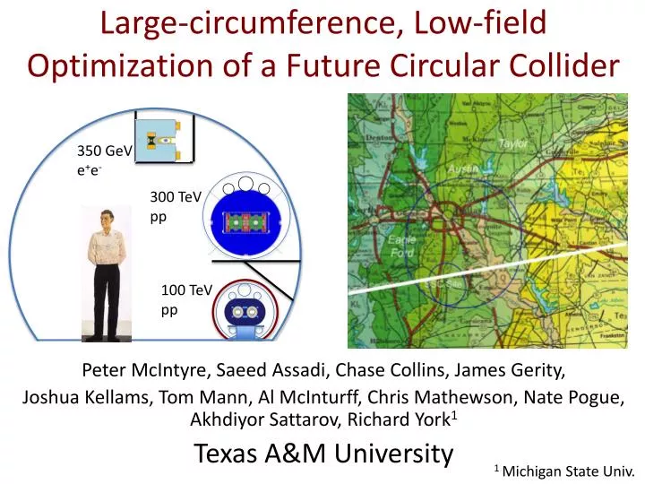
350 GeV e + e -. Large-circumference, Low-field Optimization of a Future Circular Collider. 3 00 TeV pp. Peter McIntyre, Saeed Assadi, Chase Collins, James Gerity, Joshua Kellams, Tom Mann, Al McInturff, Chris Mathewson, Nate Pogue , Akhdiyor Sattarov, Richard York 1

E N D
350 GeV e+e- Large-circumference, Low-field Optimization of a Future Circular Collider 300 TeV pp Peter McIntyre, Saeed Assadi, Chase Collins, James Gerity, Joshua Kellams, Tom Mann, Al McInturff, Chris Mathewson, Nate Pogue, Akhdiyor Sattarov, Richard York1 Texas A&M University 100 TeV pp 1 Michigan State Univ.
Present FCC design studies assume a tunnel circumference of 80-100 km. • 80 km tunnel circumference is fine for a Higgs factory, and we have one we would like to offer you… • 80-100 km circumference is a painful choice for a 100 TeV hadron collider because it pushes magnet technology to 15 T, and has very high synchrotron radiation into the aperture. • Is that really the most cost-effective choice? Suppose one proceeded with an 80 km Higgs factory, and sought a larger circumference for the next step to an ultimate hadron collider…
One final word of warning: What you want What you may get Sciencereturn Funding probability It is imperative that the project be optimized for maximum benefit and minimum cost… Scope or cost
Cost drivers for FCC-hh Capital cost: Superconducting magnets M(R) strong function of radius R Tunnel T(R) very high if it goes beyond geographic bounds, otherwise T(R) depends upon geology ~G/R Operating cost: Electricity dominated by refrigeration of heat load Q(R) Philippe Lebrun
Performance • Collision energy E(R)--providing we have enough luminosity to do the physics… The cost and performance drivers all couple to the choice of radius R for the collider, which in turn is determined by the choice of magnetic field R = E/B I am going to show you how the project cost and performance can be strongly driven by these parameters
Tunnel cost depends strongly upon the rock in which you tunnel LEP tunnel cost ~11,000SF/m in 1981 There is already an 80 km circumference tunnel in Texas – the SSC tunnel was nearly completed. The tunnel is contained in the Austin Chalk and the Taylor Marl – two of the most favorable rock types. Tunneling the SSC set world records for tunneling advance rate – 45 m/day. That record holds today! A 270 km tunnel can be located at the same site, entirely within the Austin Chalk and Taylor Marl, tangent to the SSC tunnel as injector. 270 km x $3000/m = $810 million
We have explored what the FCC collider complex would be like in a 270 km tunnel 100 TeV hadron collider requires 4.5 T magnets • RHIC dipole (3.5 T @ 4.5 K) is simple, single-shell cosq, • We have designed block-coil cosq for simple fabrication. Option: Use Nb3Sn, operate at 8-10 K • eliminate liquid He from tunnel • reduce helium inventory x7 • Reduce refrigeration power x2
We have devised a way to combine the simplicity of the superferric block-coil dipole with the superconductor efficiency of cosq. • It uses 18 turns of 21 kA cable. • It is a block-coil dipole, it is a cosq dipole. • Nb3Sn version operates at 8 K • 2x less refrigeration, 7x less He, 7x more stability • But 3x conductor $ • Total cross-section of superconducting strand in one dipole is 4.5 cm2. Compare to 40 cm2 for LHC, >80 cm2 for 15 T. • 2300 tons of superconductor for 270 km double-ring. :=) :=(
Block-coil cosq Collider Dipole All multipoles are ~10-4 cm-n for 1-4.5 T. It is a block-coil dipole: all layers wound as racetrack pancakes low AC losses – fast ramping It is a cosq dipole: minimum quantity of superconductor
The superferric dipole coils can be wound as flat pancake racetracks, then flare the endsSimple to fixture, Simple to build.
Superconductor cross-section vs. field for example collider dipole designs Nb3Sn@8K ≅ 1.8x NbTi@4.5K The dipole can be built with either NbTi@4.5K, or Nb3Sn@10Kwith 8 cm2 superconductor, or Nb3Sn@8K with 4.5 cm2 superconductor. Choice will balance issues of coil fabrication (heat treat vs. none, stability, refrigeration costs.
Superferric 4.5 Tesla dipole can be opened to a C geometry to let the heat out… The C geometry requires 5.5 cm2 superconductor vs. 4.5 cm2 for block cosq.
Refrigeration power depends strongly upon the Carnot efficiency: Q(T) = (300/T)n • Refrigeration removes synchrotron radiation heat at an intermediate temp TS ~ 60K, • Cold mass heat at TC = 2K, 4K, 8K • The choices of TS, TC determine Q… With B = 5 T, we can make a C dipole, in which we can bring the synchrotron radiation out and capture at ~room temp.
Parameters of the hadron colliders for medium and large circumference 350 GeV e+e- 300 TeV pp 100 TeV pp • For 100 km circumference, luminosity will be limited by refrigeration of synchrotron heat. • For 270 km circumference, synchrotron radiation power is reduced x3. • If we use magnets with Nb3Sn@10K, refrigeration power will not limit luminosity…
Luminosity leveling for 300 TeV FHC • Synchrotron damping dominates the evolution of tune shift and luminosity for the 300 TeV case. • Beam begins x/y symmetric, and damps in y within ~30 min – y tune shift increases, luminosity increases • Program by to maintain ~constant xy ~ .01
So let’s return to cost:and performance: R = 270 km:FCC-hh1: 5 Tesla: 100 TeV 5x1034 cm-2s-1and for our children… FCC-hh2: 15 Tesla:300 TeV 1035cm-2s-1
For a cost/performance optimization, it is unwise to lock the ring circumference • I have presented a quantitative example that there is a site where a 270 km circumference can stay in favorable rock for world-mimimum tunnel cost. • I have shown that 4.5 Tesla dipoles can provide ample aperture and open geometry for synch rad, with an amount of superconductor that is 15 times less than 15 T. • I have shown that the 4.5 T dipole can operate at TC = 8 K, doubling its Carnot efficiency, • I have shown that the C geometry can remove synch rad at TS ~ 200 K, tripling its Carnot efficiency. • And the larger circumference will enable our children to bring 15 Tesla to triple the energy for a new generation… We need to truly optimize cost and performance.
The 100 TeV hadron collider needs a rapid-cycling injector.The 5 T 10 K dipole is an excellent candidate.Example: 5 TeV injector in LHC tunnel Cos q dipole: Flux is face-on to cables Block-coil dipole: Flux is edge-on to cables
Coupling currents can be controlled by orienting cable field, coring cable
85% SS @ .0.75 T/s A first taste of the benefits:TAMU2 ramped to 0.75 T/s current data lost in DAQ bolt arc on current bus Conductor, cabling not optimized to minimize ac losses… or was it? Let’s see what could be done to optimize for rapid cycling.
AC losses arise from several sources • Coupling currents between strands in cable • Block-coil configuration + cored cable can control coupling currents between strands • Hysteresis within subelements: • need small subelement size • Coupling between subelements: • need optimum matrix resistance
Flux plate redistributes flux to suppress multipoles from persistent currents, snap-back
Optimum design using block-coil Nb3Sn fine-filament supercritical He cooling channels Nb3Sn 7.6 T/s with T = 0.5 K, 48 W/m
Summary • We have devoted a decade of magnet R&D toward high-field dipoles for hadron colliders. • We have identified a candidate site that could accommodate a 270 km tunnel for a 100 TeV hadron collider (using 5 T dipoles). • That tunnel could accommodate a 300 TeV upgrade. • We have developed a design for a 5 T block-coil cosq dipole that is simple/low-cost to build, operates at 10 K, rapid-cycles. • We are asking Texas to offer to complete the tunnels for FCC. • If we succeed we would like to solicit the FCC team to take a leadership role in developing the design and doing the R&D • If we fail we would like to develop our 5 T dipole as a candidate rapid-cycling dipole for your injector. • Either way we want to join the FCC team, and we request your endorsement to DOE that they fund us for our roles.
First we must dig out the shafts and recover the existing tunnel • 20 years ago Congress ordered the shafts to be filled with crushed rock. • The tunnel has filled with water. • But the rock of these tunnels is stable, the tunnel should be the same today as when it was built, and we know how to dig rock from a hole and pump water…