Download
1 / 88
880 likes | 972 Views
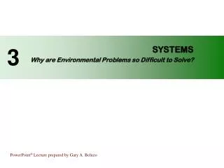
ECE362– Principles of Design The System Engineering Process. Systems. Unit Overview. The systems challenge System concepts and terms Diagrams for systems Actors, boundaries, interfaces. >>The Systems Challenge<<. The Man-Made World Is Increasingly Populated by Systems.

E N D
ECE362– Principles of Design The System Engineering Process Systems
Unit Overview • The systems challenge • System concepts and terms • Diagrams for systems • Actors, boundaries, interfaces
>>The Systems Challenge<< The Man-Made World Is Increasingly Populated by Systems • Transportation, Energy & Power Systems • Manufacturing, Construction Systems • Telecommunication Networks • Man-Made Biological, Health, and Personal Care Systems • Facility, Properties • Business Processes • Other Man-Made and Natural Systems
>>The Systems Challenge<< These Systems Are Becoming More Complex • Under pressure of demand & competition • Enabled by progress in technology • Becoming more complex at exponentially growing rates
>>The Systems Challenge<< The Growth Of Systems Complexity Eventually Can Outpace Human Ability To: • Describe • Predict • Manage • Monitor • Configure • Evolve • Understand • Install • Operate • Repair • Maintain • Account For • Communicate About • Design and Implement • Manufacture • Diagnose • Control • Maintain Security Of Those Systems must be produced . . .
>>The Systems Challenge<< . . . At Least Within Reasonable: • Time • Cost • Effort • Sense of Security from Risk
Systematica Metaclass The system perspective • A System is a collection of interacting Components : System Interaction Relationships Components
What does “interact” mean? • Components are said to interact if one one component can impact the state of another. • Components that do not impact each others’ states are said to be isolated or non-interacting. Interacting Interactions Impact Component States System Non-interacting Components
What does “state” mean? • The state of a component helps determine its externally visible future interactive behavior. • States are values of component state variables, such as: • Temperature, Pressure, Density • Position, Velocity, Acceleration • Happiness, Frustration, Satisfaction • Profitability • Voltage, Current • Asleep, Awake • Empty, Full Components and systems have states. System Components
Systems may use any technology • Mechanical • Electronic • Software • Chemical • Thermodynamic • Human organizations • Biological
Example system • System: Semi-trailer truck hauling freight • Components: engine, power train, suspension, lubrication system, fuel system, braking system, electrical system, cab, trailer, navigation system, communication system, software modules • Interactions: mechanical support, electrical power dependency, control interaction, mechanical drive, thermal interaction
Example system • System: Telecommunication services system • Components: telephones, modems, workstations, transmission links, circuits, switches, base stations, communication sessions, software, customer requests, billing systems, customer analysts • Interactions: electrical & optical physical interactions, symbolic trunk status signaling, mechanical mounting support, power dependency, fault propagation
System Subsystem Subsystems • A Component can itself be a System • This just means the Component has Components. • This makes it a Subsystem of the first system. • This can continue indefinitely. • Where does it stop?
System Subsystem Where does it stop? • It does not stop — we do! • These are modeling constructs—ideas in our heads. • We are using the System Perspective: • How we have chosen to think about a system.
Is everything a system? • Is a rock a system? • Does it have parts? Interactions? • If you are a geologist, a rock is a system: • Strata, crystals, chemical interactions, pressures • But, if you are using the rock in your slingshot, this is not useful to know! • Different people need different models for different purposes • Views of models
What to model? • In model based systems engineering, it is not enough for a model to be correct: • We also have to ask if a model is useful to us. • We only need to model what is useful, to sort out requirements, plan designs, communicate specifications, verify behavior, etc. • There is a tendency of new modelers to model too much, to include too much detail …. so watch out!
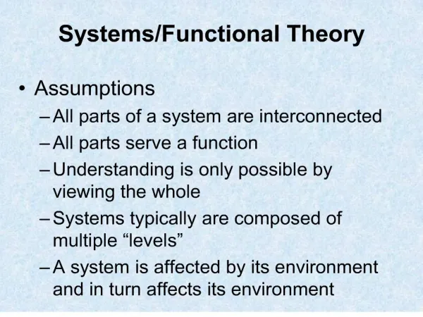
System Interaction Relationships Components The System Perspective • Some definitions of the concept of system include not only: • that there are components, • and that there is a framework of interaction relationships, • but also these additions: • that a system exists for a purpose and has a body of rules about it.
System Interaction Relationships Components The System Perspective • Systematica formally models intelligence and the actual management of systems, including both man-made and natural systems: • So, we consider ideas such as “purpose” and “rules” to be part of other (extended) systems that we will model later in this workshop, including use of other Metaclasses. • Thus, we only need to remember that a system is a collection of components and their interaction relationships:
Naming and defining systems • Systems have names and definitions: • System name: a brief noun phrase • System definition: one or a few sentences • Example: • System name: Acme Model 17 Lawnmower • System definition: The lawnmower product model sold by Acme Lawnmower Company for mid-range commercial applications.
Environment System Logical Systems • A Logical System is a system identified based solely upon its required functionality (its behavior as seen by external systems interacting with it), and not based upon how it achieves that functionality internally or its identity or physical make-up.
Environment System Logical Systems • Logical Systems are typically named and defined without reference to proper names (product, people, organization names). They are typically defined without reference to their physical composition (unless--in a few cases--this is a part of the externally required behavior). General name for a TYPE of system.
Environment System Logical Systems • Example of Logical System: • Engine System: An Engine System converts atmospheric air and chemical fuel into rotating mechanical power for use by other machine subsystems.
Physical Systems • A Physical System is a system defined based upon its physical identify or physical composition. Physical Systems may be given proper names, such as names of commercial products, corporate systems, people, organizations, buildings, etc., i.e. a SPECIFIC system.
Physical Systems • Examples of Physical Systems: • Model 3406 Engine • Building 407 • Program Module 1750
Physical and Logical Systems • A Logical System is equivalent to a functional role. • Physical Systems may be assigned responsibilities to perform roles that are Logical Systems. Example of Logical System: Engine System: An Engine System converts atmospheric air and chemical fuel into rotating mechanical power for use by other machine subsystems. Example of Physical Systems: Model 3406 Engine: The Engine System sold by Caterpillar Inc. into the mid-range industrial market.
Physical and Logical Systems • What is are examples of RHIT ECE physical systems? • ECE 300 Course • ECE 320 Course • ECE 340 Course • ECE 360 Course • What are example RHIT ECE logical systems? • Communications systems sequence • Control systems sequence • Electromagnetics sequence • Design sequence
System diagrams • Formal diagram notation: • UML subset--UML class/object diagrams • Frequently used system diagrams: • System environment diagram • System domain diagram • System logical architecture diagram • System physical architecture diagram (physical deployment diagram)
System diagrams • System environment diagram: To illustrate the systems (called “actors”) outside a “subject system”, with which it interacts. • System domain diagram: To illustrate the important relationships between the actors for a subject system (domain knowledge).
Environment System Actors, boundaries, interfaces • Actors: The systems external to a subject system, with which it directly interacts. • System Boundaries: The set of all actors for a subject system constitutes its formal boundary. This is often informally illustrated with a line boundary dividing the system from its environment:
Interfaces Environment System Actors, boundaries, interfaces • System Interfaces: We will formally define interfaces in a later unit, but show their graphical appearance for now.
State B causal event 2 causal event 1 State C State A causal event 3 States • A State is a system condition, situation, or mode, that has existence for a length of time. The state of a system determines in part its future behavior. • The time history of states of systems can be described using “trajectories” of states: • finite state machines, or • continuous paths in phase space. State transition diagrams, or (UML) state charts, can be used to graphically describe finite state machines.
States • State transitions are graphically illustrated links indicating the passage of a system from one state to another. • Events are occurrences in time. • Events can be modeled as the cause of state transitions, by labeling state transition lines with event names. Event Name State B State Transition causal event 2 causal event 1 State State C State A causal event 3
Organizing functions with states • Functions can be associated with states. • This is a way to indicate what functional interactions are required to occur during certain situations (that is, “when” they should occur in time) • This is a way to connect the (software engineering) “use case method” to state and function modeling techniques
Lawnmower example Starting Mowing Shutting Down Functions: 1.Cut grass (to operator determined length) 2. Noise control (conform to ASPE 102.3 noise guidelines) 4.Emission control (conform to EPA 11.2 emission guidelines) Functions: 1. Start (w/i 10 seconds of turning key) 2.Check Starting Interlocks (blades must be disengaged) 3. Noise control (conform to ASPE 102.3 noise guidelines) 4.Emission control (conform to EPA 11.2 emission guidelines) Functions: 1. Disengage blades 2. Shut down engine
Environment System ECE362 Principles of Design The System Engineering Process Requirements
Requirements Overview • This unit overlaps and utilizes the ideas of the previous units, to assemble the metaclasses into requirements supporting structures, emphasizing the HLR Process. • Content: • Requirements versus design • High level requirements (HLR) process • Detail level requirements (DLR) process • Analysis: decomposition of functions, states, systems • Assembling specification documents
Customer/Market Needs Available Technologies Requirements-design iteration Design Specification (“Design”) Requirements Specification (“Analysis”) design impacts requirement structure refinement refinement
Engineering processes • This section will particularly focus on model-based methodology for representing high level requirements and high level design frameworks.
Environment System Requirements (or PDS) • Statements at external boundary of subject system • What we want the system to be or do
Environment System Design • Statements about internalphysicalcomponents and theirinteractionrelationships • How we are going to meet requirements
Environment System Interfaces • Connect internal components to external components or actors • Help us group attributes and behaviors seen externally
Design statement Requirement statement Detailed design statement Detailed requirement statement More detailed design statement More detailed requirement statement Inside vs. outside Design Interfaces Requirements Environment System Detail does not equal design
Environment System Inside vs. outside, continued • Reference boundaries • One person’s design is another person’s requirement
An SE benefits “sweet spot” • The High Level Requirements (HLR) and High Level Design (HLD) processes require less time and effort than their detailed counterparts. • However, there is typically a very high return on this investment. • Many organizations utilize extensive detailed specifications, but don’t have HLR and HLD specifications. • This means that there is not a unifying framework structure, shared mentally by all concerned, that simplifies and organizes the detailed specifications. • HLR/HLD is a “sweet spot” in the SE process, because it can rapidly begin digging an organization out of problems caused by this lack.
Generic HLR Process • Generic (unconfigured) HLR Processes: • Identify Stakeholder (Customer) Needs Process • Identify System Environment Process • Identify Features, Services Process • Identify Use Cases Process • Identify Functions Process • Identify Scenarios Process • Analyze Logical Architecture Process • Repository and Specification Assembly Process (Validation and verification are associated with most of these processes) • Refer to process framework drawings in handouts.
Identify stakeholder needs • Stakeholders are people or organizations with an interest (stake) in the system being specified: • Customers • Users • Operators • Maintainers • Company Owners • Regulators • Others
Identify system environment • System environment diagram: • Subject System--system whose requirements are to be specified • Actors--interacting systems external to the Subject System • Boundary defines system by defining what it is not--listing the external interactingactors • Often harder than it looks: • Often skipped as “obvious” • Later source of confusion Actor Actor Actor SubjectSystem Actor Actor
Identify system environment • Domain diagram identifies relationships between actors that are important to system requirements • Explicitly models “domain knowledge” about the environment • Establishes the semantics of the subject system specification to follow Actor Actor Actor SubjectSystem Actor Actor
Environment System ECE362 – Principles of Design The System Engineering Process High Level Design