Download
1 / 32
320 likes | 378 Views
Combinational Circuit ATPG based on PODEM. Ziqi Zhou Auburn University Department of Electrical and Computer Engineering 3/23/2016. Combinational Circuit ATPG based on PODEM. Why we need to test chips? What is ATPG? Combinational circuit ATPG algorithm How PODEM works in a circuit

E N D
Combinational Circuit ATPG based on PODEM Ziqi Zhou Auburn University Department of Electrical and Computer Engineering 3/23/2016
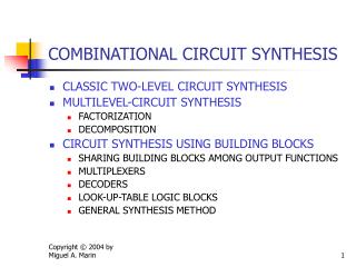
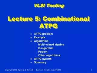
Combinational Circuit ATPG based on PODEM Why we need to test chips? What is ATPG? Combinational circuit ATPG algorithm How PODEM works in a circuit Result Future work References 2
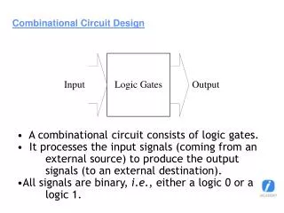
Combinational Circuit ATPG based on PODEM • Why we need to test chips? • Many integrated circuits contain fabrication defects upon manufacture • Die yields may only be 20-60% for high end circuits • ICs must be carefully tested to screen out faulty parts before integration in systems • Latent faults that cause early life failure must also be screened out through “burn-in” stress tests • Only focus on combinational circuits 3
Combinational Circuit ATPG based on PODEM • What is ATPG? • ATPG(Automatic test pattern generation) is an electronic design automation method/technology used to find an input (or test) sequence that, when applied to a digital circuit, enables automatic test equipment to distinguish between the correct circuit behavior and the faulty circuit behavior caused by defects. • Fault models: • The Stuck-at faults • Transistor faults • Bridging faults • Only focus on stuck at faults 4
Combinational Circuit ATPG based on PODEM • Combinational Circuit ATPG algorithm: • D-algorithm • The D Algorithm was the first practical test generation algorithm in terms of memory requirements. The D Algorithm [proposed by Roth 1966] introduced D notation, which continues to be used in most ATPG algorithms. D algorithm tries to propagate the stuck at fault value denoted by D (for SA0) or D’ (for SA1) to a primary output. • Podem • Path-Oriented Decision Making (PODEM) is an improvement over the D Algorithm. PODEM was created in 1981, by Prabhu Goel, when shortcomings in D Algorithm became evident because design innovations resulted in circuits that D Algorithm could not test. • More efficient algorithms: FAN algorithm 5
Combinational Circuit ATPG based on PODEM • The advantage of PODEM: • Expand binary decision tree only around primary inputs • This reduces size of tree from 2n to 2num_PI • D-ALG failed to generate test for these circuits • Search too undirected • Large XOR-gate trees • Must set all external inputs to define output 6
Combinational Circuit ATPG based on PODEM • PODEM High-Level Flow: • 1. Assign value to an unassigned primary input • 2. Determine all implications of assignment • 3. If test is generated, exit; else • 4. Is test is possible with additional input assignments ? • fault site doesn't have fault value assigned • Path of unassigned leads from D (D’) to an output • If yes, go to 1, if no • 5. Change input assignments to untried combination, go to 2 • If no untried combination exists — untestable fault 7
Conbinational Circuit ATPG based on PODEM About the program : Using c++ code. Works in Linux Using gcc compiler 8
Conbinational Circuit ATPG based on PODEM Read circuit: For example, if the first column is 0 then it's a gate. Second column is the output of the gate. Outline, also called line number, is unique. Third column is the type of the gate. Column 4 is the number of fan-out (how many outputs this gate drives. )The fifth column is the number of inputs to the gate. Column 6-N are the line numbers of the inputs to the gate. Similarly for PI (Primary input of the circuit), PO (Primary output of the circuit) and BR (Branches). 9
Combinational Circuit ATPG based on PODEM Read circuit: (Cont.) 10
Combinational Circuit ATPG based on PODEM How PODEM works in a circuit: 11 Step 1:Select path s – Y for fault propagation
Combinational Circuit ATPG based on PODEM How PODEM works in a circuit: • Step 2: Initial objective: • Set r to 1 to sensitize fault 12
Combinational Circuit ATPG based on PODEM How PODEM works in a circuit: 13 Step 3: Backtrace from r
Combinational Circuit ATPG based on PODEM How PODEM works in a circuit: 14 Step 4: Set A = 0 in implication stack
Combinational Circuit ATPG based on PODEM How PODEM works in a circuit: 15 Step 5: Forward implications: d = 0, X = 1
Combinational Circuit ATPG based on PODEM How PODEM works in a circuit: 16 Step 6: Initial objective: set r to 1
Combinational Circuit ATPG based on PODEM How PODEM works in a circuit: 17 Step 7: Backtrace from r again
Combinational Circuit ATPG based on PODEM How PODEM works in a circuit: • Step 8: Set B to 1. • Implications in stack: A = 0, B = 1 18
Combinational Circuit ATPG based on PODEM How PODEM works in a circuit: • Step 9: Forward implications: • k = 1, m = 0, r = 1, q = 1,Y = 1, s = D’, u = D’, v=D’, Z = 1 19
Combinational Circuit ATPG based on PODEM How PODEM works in a circuit: • Step 10: X-PATH-CHECK: • paths s – Y and s – u – v – Z blocked 20
Combinational Circuit ATPG based on PODEM How PODEM works in a circuit: 21 Step 11: Set B = 0 (alternate assignment)
Combinational Circuit ATPG based on PODEM How PODEM works in a circuit: • Step 12: Forward implications: • d = 0, X=1, m = 1, r = 0, s = 1, q = 0, Y = 1, v = 0, Z = 1 • Fault not sensitized 22
Combinational Circuit ATPG based on PODEM How PODEM works in a circuit: 23 Step 13: Set A = 1 (alternate assignment)
Combinational Circuit ATPG based on PODEM How PODEM works in a circuit: 24 Step 14: Backtrace from r again
Combinational Circuit ATPG based on PODEM How PODEM works in a circuit: • Step 15: Set B = 0. • Implications in stack: A = 1, B = 0 25
Combinational Circuit ATPG based on PODEM How PODEM works in a circuit: • Step 16: Forward implications: • d = 0, X = 1, m = 1, r = 0. • Conflict: fault not sensitized. Backtrack 26
Combinational Circuit ATPG based on PODEM How PODEM works in a circuit: 27 Step 17: Set B = 1 (alternative assignment)
Combinational Circuit ATPG based on PODEM How PODEM works in a circuit: • Step 18: Forward implications: • d = 1, m = 1, r = 1, q = 0, s = D’, v = D, X = 0, Y = D’ • Test found 28
Combinational Circuit ATPG based on PODEM How PODEM works in a circuit 29
Combinational Circuit ATPG based on PODEM • Future works: • Make it work on XOR and XNOR gates. • Improve this program, make it work not only on combinational circuits, but also on Sequential circuits. 30
References • M.L. Bushnell, V.D. Agrawal, Essentials of Electronics Testing for Digital, Memory & Mixed Signal VLSI Circuits, Kluwer Academic Publishers, Boston MA, 2000 • P. Goel, “An Implicit Enumeration Algorithm to Generate Tests for Combinational Logic Circuits,” IEEE transactions on Computers, Vol. C-30, no. 3, pp. 215-222, 1981 • P. Goel, B.C. Rosales, “ PODEM-X: An automatic test generation system for VLSI logic structures,” Proceedings of the 18th conference on Design automation, pp. 260- 268, 1981 • Wang, Wu and Wen (2006) VLSI Test Principles and Architectures: Design for Testability. San Francisco: Morgan Kaufmann Publishers 31
Thank you! 32