Download
1 / 34
350 likes | 622 Views
System Design Constraints, RAM-T, a Paradigm Shift. Vern Fox United Defense LP. Agenda. RAM-T Overview Legacy Methods Legacy Results Paradigm Shift: RAM-T Case Implementation. RAM-T Overview. What is RAM-T

E N D
System Design Constraints, RAM-T, a Paradigm Shift Vern FoxUnited Defense LP
Agenda • RAM-T Overview • Legacy Methods • Legacy Results • Paradigm Shift: RAM-T Case • Implementation
RAM-T Overview • What is RAM-T • Reliability - The ability of a system or component to perform its required functions under stated conditions for a specified period of time. • Availability – the ability of a product to be ready for use when the customer wants to use it (uptime/uptime+downtime) • Maintainability - the relative ease and economy of time and resources with which an item can be retained in, or restored to, a specified condition when maintenance is performed by personnel having specified skill levels, using prescribed procedures and resources at prescribed level of maintenance and repair. • Testability – A design characteristic which allows the status (operable, inoperable or degraded) of an item to be determined and the isolation of failures within the item to be performed in a timely manner. • System Design Constraints
Legacy Methods Legacy Approach Eliminate some component RAM-T drivers Fix integration issues Update design Eliminate some component RAM-T drivers Fix integration issues Update design • Perform predictions • Based on handbook data • Based on similar equipment • Address SOME RAM-T drivers • RAM-T optimized during test • Low initial RAM-T • High test hours, high $’s Late identification of component RAM-T shortcomings limits corrective action System Int and Test Assessments Subsystem Int Preliminary Design Detailed Design Test Fielding
Legacy Results Only 30% Success (Data 1996 - Oct 01) Of Failed Tests, 75 % Of Systems Failed to Achieve Even Half Of Their Requirement!
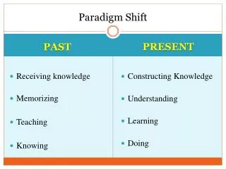
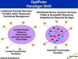
Paradigm Shift: RAM-T Case • Legacy methodologies failing • Methodology required for infusing RAM-T into design • Criteria • Early, influence design during design phase • Return on Investment (ROI) • Result: Paradigm Shift – RAM-T Case • Make case for how RAM-T requirements will be met • Combination of analyses and tests • Physics of Failure (PoF) analyses • RAM-T Enhancement Tests (RET) • RAM-T Case Management Plan • RAM-T Case Report • Elevate RAM-T constraint importance
Paradigm Shift Legacy Approach Eliminate some component RAM-T drivers Fix integration issues Update design Eliminate some component RAM-T drivers Fix integration issues Update design Late identification of component RAM-T shortcomings limits corrective action System Int and Test Assessments Subsystem Int Preliminary Design Detailed Design Test Fielding RAM-T Case Approach Eliminate component reliability drivers Update design Fix integration issues Update design Eliminate component reliability drivers Update design Fix integration issues Update design Early identification and elimination of component level failures SystemInt and Test PoF RET SubsystemInt Emphasize: Early identification and elimination of RAM-T shortcomings Example: Achieve Higher Mi on prototype delivery
Paradigm Shift: RAM-T Case • Make case for meeting RAM-T requirements • Documented in RAM-T Case Management Plan • A living document, updated throughout the program • Plan and supporting data subject to approval • RAM-T requirements are clearly understood • Methods/activities to be performed to make case • Ensure RAM-T is key factor in the design process • Ensure RAM-T is of equal weight with other engineering disciplines • RAM-T Case Report • A living document, updated throughout the program • Reasoned, auditable documentation of progressive assurance that RAM-T requirements will be met • Audit trail of engineering considerations, trade studies, analyses and assessments
Paradigm Shift: RAM-T Case • A RAM-T Case Program/Plan sample contents • Benchmarking RAM-T Requirements • Dynamic/static design modeling, simulation, or probabilistic analysis • Critical component identification • RAM-T Modeling, Optimization and Component/System Testing • Environmental stress (operate and storage) • Physics-of-Failure (PoF) • Structural finite-element stress analysis • Fatigue analysis • Wear-out/service life analysis • Long-term storage (shelf life) assessment • Prognostics analysis • Fault detection/isolation analysis • Built-in Test False alarm rate analysis • Availability Analysis • On-board Sparing: Supportability analysis • RAM-T Block Diagram • RAM-T Assessments Analysis • Risk assessment & mitigation • Diminishing resources/obsolescence plan • Pit Stop Engineering
Paradigm Shift: RAM-T Case • RAM-T Case Management Plan • Methods/activities to be performed to make case • Goal - Robust designs • Physics of Failure (PoF) • Finite Element Analysis (FEA) • Fatigue Analysis • Probabilistic Analysis • calcePWA Analysis • Pit-Stop Engineering • RAM-T Enhancement Testing (RET) • Highly Accelerated Life Testing (HALT) • Accelerated Life Testing (ALT)
Engineering-Based Reliability • Physics of Failure, • -Model the root causes of failure (e.g., fatigue, fracture, corrosion & wear) • CAD tools developed - By industry/academia/government - To address specific materials, sites, & architectures Stress (e.g., vibration) is propagated from system level to failure site • Benefits • Design-in reliability • Eliminate failures prior to test • Increased fielded reliability • Decreased O&S costs Root-cause failure is cracking of solder joint
Software Tools Finite Element Modeling Solid Modeling Dynamic Simulation Electronic Circuit Card and IC Toolkits Fatigue Analysis Thermal Fluid Analysis
Physics of Failure to Evaluate Electronics Enclosure Design Circuit Card Design Vibration/Shock Environment Computational Fluid Dynamics Model CalcePWA Circuit Card Tool Thermal Conditions Determine if electronics are acceptable based on analysis Determine if circuit card or enclosure can be redesigned to eliminate failure mechanism PoF-Based ESS Accelerated Life Testing on critical board or IC failure mechanisms
Computational Fluid Dynamics (CFD) Modeling • Examples: ICEPAK, FLOWMAX, University of Maryland CalceCFD • Inputs • Exterior ambient air temperature • Initial temperature • Fan properties • Power dissipated for each CCA • Outputs • Interior air velocity • Interior air temperature • CCA edge temperature Outputs from CFD analysis used as boundary conditions for CCA thermal modeling
Architecture & environment modeling Reports and documentation Toolbox Failure assessment & sensitivity analysis Vibration analysis Thermal analysis UMD CalcePWA Software Tool
Electronics Circuit Card Success Stories Tracked Vehicle Increased Reliability $1.2M Saved Radar Ground Station • Identified potential thermal & vibration problems • Analysis showed commercial circuit card OK Air & Ground System Electronics $27M Cost Avoidance Tri-Service Radio Design Changes Recommended • Identified weak link in design & verified • Validated with testing • Circuit card & thermal box-level analyses • Identified problems & ensured reliable expansion of capability Army Helicopter $50M Savings Missile System • Air Force analysis showed commercial ICs OK • Analysis on Plastic Ball Grid Array IC package Evaluate New Technology
Fatigue Analysis Using Dynamic Simulation & FEA Dynamic Load Analysis Solid Modeling Dynamics Analysis System Model Terrain Model DADS Pro/E Component Stress Analysis FE Model FEA NASTRAN Reliability Analysis Reliability Based Design Optimization Fatigue Life Assessment List of Critical Nodes DRAW
Three-Dimensional CAD Solid Models CAD: Pro/Engineer, AUTOCAD, I-deas, Solidworks, • Used for design and manufacture • Used to develop Finite Element Analysis & Dynamic Analysis models
Finite Element Analysis (FEA) Models Examples: NASTRAN, ANSYS, ABACUS, Pro/Mechanica, I-deas • Calculates vibration modes • Calculates stress and strain • Input into fatigue analysis • Used for structural stress evaluation Mode 1 Mode 2
Flexible-Body Dynamic Analysis Model • Examples: DADS & ADAMS • Multi-body approach • Use input from solid model & FEA model • Experimental data used for model inputs of tire, shock absorbers & suspension • Determines force/ acceleration time history at all locations on trailer Vehicle traversing simulated terrain profile Input into FEA & fatigue analyses
Fatigue Analysis Software • Examples: nCode, LMS, University of Iowa DRAW • Edits & characterizes strain time histories • Rainflow counting & mean stress correction of strain cycles • Estimates plastic strain based on elastic stress or strain calculations • Calculates fatigue life based on measured (strain gauge) or FEA strain time histories
Trailer Physics-of-Failure Project Fatigue life estimates of drawbar consistent with failure data Life (Blocks) Critical Point White represents low fatigue life Benefits: • Early identification of failure modes • Better test planning and design • Improved maintenance procedures Enlargement of Critical Region
Paradigm Shift: RAM-T Case • Pit-Stop Engineering • User/Maintainer hardware interface as a key design parameter • Develop Standards of Excellence • Defines the critical parameters • Examples • 37 pounds maximum for an electrical assembly. • Spares on board to provide on board failure recovery. • Placement of electronics should be on exterior man accessible surfaces, no buried electronics. • No cables in places where they cannot be accessed. • Use common connectors throughout. • Etc. • Visualization for decision making
Paradigm Shift: RAM-T Case • Reliability Enhancement Testing (RET) • Testing focused on Reliability improvement • Objective • Find failure modes • Eliminate failure modes • Mitigate those not able to eliminate • Period of performance • Once hardware is available • Methodologies • Use up the life of the product • Normal use (years) • Accelerated life test (weeks or months) • Highly accelerated life test (days)
Load Levels Upper Destruct Limit Upper Operating Limit Upper Destruct Margin Upper Design Limit Upper Operating Margin Upper Design Upper Specification Limit Margin Nominal Lower Specification Limit Lower Design Margin Lower Design Limit Lower Operating Margin Lower Destruct Margin Lower Operating Limit Lower Destruct Limit Paradigm Shift: RAM-T Case
Paradigm Shift: RAM-T Case Test Equipment Providing real-time status of UUT performance Environmental Stress Chamber with Unit Under Test (UUT) Powered-up and Functioning under load
Implementation • Embrace the philosophy • Determine critical items • Put together multi-disciplined team • Reliability Improvement Working Group (RIWG) • Determine RAM-T Case methodologies • Document in Action Plan
Implementation • Reliability Improvement Working Groups • Integrated, collaborative team composed of design, specialty, and test personnel to develop Action Plans for critical components to improve the reliability early in the design process. • Action Plans cover proactive reliability tasks such as design reviews, load/stress surveys, failure mode analysis, physics of failure, probabilistic analysis, and reliability enhancement testing. • Forum for discussing Action Plans with and receiving input from reliability improvement experts from customer, OPM, AMSAA, AEC, and other government and industry organizations.
Implementation • Risk Mitigation & Proactive Reliability Tasks Note: Planned through March 2004 unless otherwise indicated Note (1): Planned by PDR
Emerging Findings, Physics of Failure, FEA Recoil Seal Implementation The gaps show that the whole surface area is not being used to seal.
Emerging Findings, RET Rammer Chain Housing Material RIWG Projected Costs Material Sample Result: Influenced material selection Significant parameters: Wear and heat buildup