Download
1 / 8
80 likes | 205 Views
Synchronization. Policy: HCAL will follow ECAL as much as possible Same TTC distribution system 6 TTCvi/TTCex, optical splitting, etc. LVDS fanout from HRC (HCAL Readout Control) card to 18 HTR cards might use coax limo connectors tho….

E N D
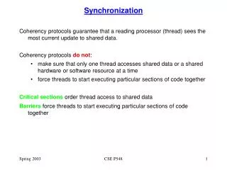
Synchronization • Policy: HCAL will follow ECAL as much as possible • Same TTC distribution system • 6 TTCvi/TTCex, optical splitting, etc. • LVDS fanout from HRC (HCAL Readout Control) card to 18 HTR cards • might use coax limo connectors tho…. • Use sync histogram technique to monitor phase stability in situ • Will try to estimate where we are different from ECAL • pulse shape • occupancies • delays • Overall guess: • we will be ok if ECAL is ok!
QIE Output • QIE clock control ASIC (CCA) • clock skewing by 1ns over 25ns • jitter is 150-200 ps • Crossing determination algorithm: • P3+P4+P5-1.5x(P1+P2) • FPGA will select when data is consistent with expected shape
P5 P4 P3 P2 P1 CCA phasing • Can adjust CCA to give “smooth” profile • .0 .0 .47 .47 .06 • this profile minimizes charge loss inside QIE • slow down slewing when switching from 1 cap to the other • or a “peaked” profile • .0 .0 .68 .29 .03 • perhaps easier for crossing determination….
“Peaked” phasing “Smooth” phasing BC HERE Crossing Determination • For L1 Trigger, use a simple algorithm: • TT = -3/2(P1+P2) + P3 + P4 + P5 • look for large change - tags beam TT ET consistent with beam crossing
Pileup • Can’t distinguish hits separated by 1 or 2 buckets, but 3 or greater ok… • due to signal being spread over 3 buckets “Smooth” phasing D bucket=4 D bucket=1 D bucket=5 D bucket=2 D bucket=3
Pileup (cont) “Peak” phasing
HCAL Occupancies • HCAL estimates occupancy at 10% for 200 MeV ET @ 1034 • HCAL needs enough large energy hits (photo statistics) for L1 threshold to get high photo statistics for synchronization histogram: • 10 photo-electrons per GeV energy • plenty, since we’re using ET for the histogram sync (except perhaps at h=0) • 1034 min bias spectrum falls exponentially with ET: • HB (0<h<1.4) P(ET) ~ e -4.9ET • from .2 to 3.0 GeV, probability drops by about 10- 6 • occupancy @ 1034 is therefore ~10-7 • takes 107 buckets to get 1 hit, need 10 hits, want 10 hits in all ~3000 buckets • therefore takes ~3x10¹¹ buckets, or about 3 hours • HE (1.4<h<3.0) P(ET) ~ e -6.4ET • photo statistics is in E, not ET so relax to 2 GeV to get similar numbers as HB
Delays • HCAL will use same algorithms as ECAL • same FPGA techniques too! • HCAL adds far fewer towers to make TPG than ECAL • Expect delays to be same, or smaller, than ECAL • Laser Pulsing • same techniques as ECAL