Download
1 / 14
140 likes | 371 Views
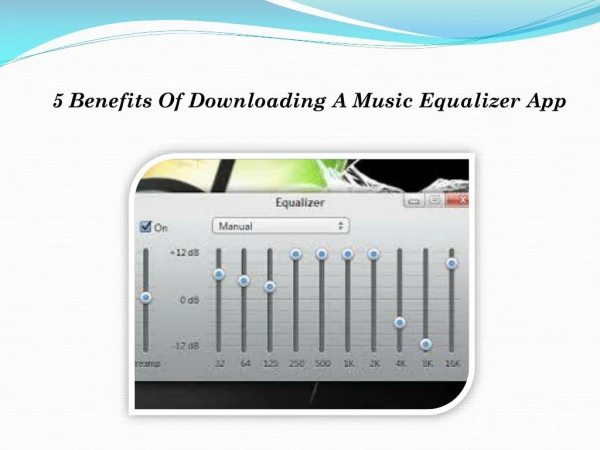
Digital 5-Band Equalizer. Electrical Engineering 113D. Authors: Gordon Tsui Michael Kim. Digital Equalizer. Used in Audio Processing and is the process of modifying the frequency envelope of sound

E N D
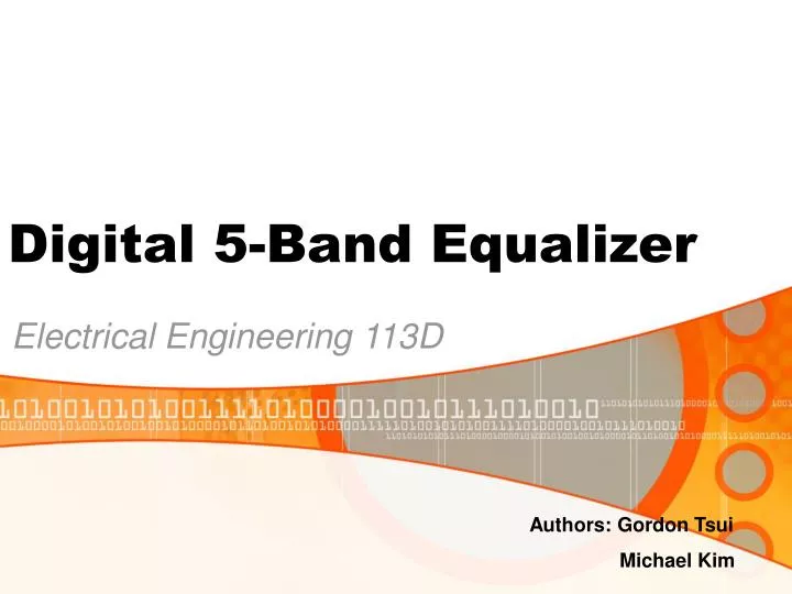
Digital 5-Band Equalizer Electrical Engineering 113D Authors: Gordon Tsui Michael Kim
Digital Equalizer • Used in Audio Processing and is the process of modifying the frequency envelope of sound • Found in various programs such as WINAMP, Windows Media Player and any other application that requires digital audio processing. • Number of bands vary on each equalizer
Development • Modeled project after Experiment 2 • Used MATLAB to obtain coefficients required for different filters • Found impulse response to verify requirement needs • Implemented assembly code and tested results
Impulse Response • Specifications needed to meet a 1dB Ripple
Filter Specifications • Our Equalizer consisted of 5-bands
Filter Specifications • Low Pass Filter – Magnitude Responses • Difference seen between two due to anti-aliasing filter in DSP Board
Filter Specifications • Band Pass Filter 1 – Magnitude Responses
Filter Specifications • Band Pass Filter 2 – Magnitude Responses
Filter Specifications • Band Pass Filter 3 – Magnitude Responses
Filter Specifications • High Pass Filter – Magnitude Responses • Difference seen between two due to FHP cutoff frequency
Assembly Code XGL .word 32767 ;the different gain valuesXGB .word 0 ;at the end of the .data sectionA = trcv ; load accumulator with wordAR1=#XLP ; AR1 points to XLP and gets value of A*AR1=AAR1=#XBP ;AR1 points to XBP and gets value of A*AR1=AAR3 = #XNLAST ;points to XNLASTA = #0 ;sets value of A to 0repeat(#122) ;123 coefficientsMACD(*AR3-,L0,A) ;same as experiment 2*AR0 = hi(A) ;AR0 gets the MSB of AA=#0 ;sets value A to zeroMACP(*AR0, XGL, A) ;multiplies values of at AR0 and XGL and stores in A*AR0 = hi(A) ;AR0 gets the MSB of AAR3 = #XNLASTBA = #0repeat(#122)MACD(*AR3-,B0,A)*AR4 = hi(A)A=#0MACP(*AR4, XGB, A)*AR4 = hi(A)A = *AR0A = A + *AR4 ;the output of the two filters are added togethertdxr = A ;value of A sent to output
Problems With Assembly Coding • Initially had too many coefficients that the DSP board couldn’t handle • Unable to use the @ operator • Gain of 1*(2^15-1) reduces signal by factor of 2
Examples • Audio Clip with unity Gain • Applied High Pass Filter • Applied Band Pass Filters • Combination of Band Pass and High Pass • Applied Low Pass Filter