Download
1 / 12
120 likes | 250 Views
Fission setup based on PPACs using a coincidence technique. L. Audouin, S. Isaev, L. Tassan-Got, C. Stephan IPN d’Orsay I. Durán, C. Paradela , D. Tarrío Univ. Santiago de Compostela (on behalf of the n_TOF Collaboration). Motivation.

E N D
Fission setup based on PPACs using a coincidence technique L. Audouin, S. Isaev, L. Tassan-Got, C. Stephan IPN d’Orsay I. Durán, C. Paradela, D. Tarrío Univ. Santiago de Compostela (on behalf of the n_TOF Collaboration)
Motivation • Fast reactors and ADS have renewed the interest on nuclear data, in particular those beyond 20 MeV. • A new generation of facilities allows studying nuclear reactions at high neutron energies. • For measuring fission, new devices are needed for discriminating fission from competing reactions ( spallation, multifragmentation,…)
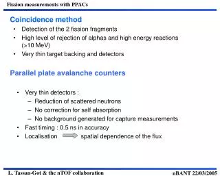
Parallel Plate Avalanche Counter (PPAC) • Very thin detectors. • High detection efficiency for heavy ions (FF) • Fast timing with anode signal (0.5 ns resolution). • Fragment position from cathode signals.
Detection setup • 10 PPACs and 9 targets (235U and 238U as references). • Gas flow inside a reaction chamber • Thin targets (300 µg/cm2) and backings (550 µg/cm2) • Both fragments detected by the closest PPACs. Trajectory reconstruction.
U-234: singles U-234: coincidences Coincidence technique Coincidence technique Coincidence condition between anode signals rejects most of the background
Fission target identification • Correlation between PPAC time differences allows the unambigous target identification T0 T0 T0 T1 T1 T1 T1 T2 T2 T2 T2 T2
Cathode positioning Diagonal condition: (Tch1-Tanode)+(Tch2-Tanode)=DLT DLT: Total delay line length (~320 ns) The time difference between both cathode ends provides the position of the signal.
Cross Section: Energy Resolution Very low background: lower yield between resonances than expected from evaluations
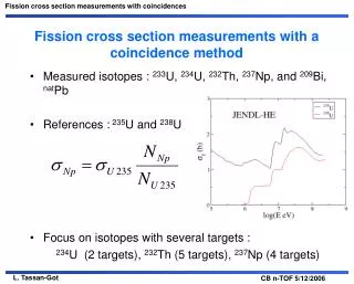
Cross Section: Energy Range • Fission measured for neutron energies up to 1 GeV. • Cross sections have been measured for different isotopes: 234,233U, 237Np, 232Th, natPb, 209Bi. [1] C. Paradela et al. Phys. Rev. C 82, 034601 (2010) [2] L. Audouin et al. Proc. of ND2007, p. 421 [3] D. Tarrío et al. Phys. Rev. C 82, 044620 (2011)
Log E =6.0 Log E =5.8 Log E =5.9 Cos () Cos () Cos () Log E =5.4 Log E =5.6 Log E =5.5 Fission Fragment Angular Distribution U-234 cosine distribution for neutron energies near the fission threshold
This work Leachman Tutin Anisotropy extrapolation B (Anisotropy parameter) Neutron energy (MeV) • Angular Distribution of fission fragments is described by W()1+Bcos2 • Results obtained fitting in our reduced angular range • Despite the constraints, present results are quite in agreement with previous data from Leachman (Phys. Rev. 137, B814 (1965)) and Tutin et al. (Nucl. Instrum. Meth. A 457 (2001) 646-652)
Conclusions • A fission detection setup based on PPACs has been implemented for the CERN n_TOF facility. • Both fission fragments are detected in coincidence and their trajectory is reconstructed. • Cross sections and angular distributions can be measured up to 1 GeV at the CERN n_TOF facility.