Download
1 / 21
210 likes | 328 Views
Snowmass ILC meeting. Micromegas TPC beam tests at KEK. A.M. Bacala, A. Bellerive, K. Boudjemline, P. Colas, M. Dixit, K. Fujii, A. Giganon, I. Giomataris, H. C. Gooc, Y. Kato, M. Kobayashi, H. Kuroiwa, V. Lepeltier, T. Matsuda, O. Nitoh, R. L. Reserva,

E N D
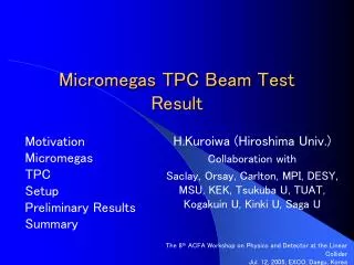
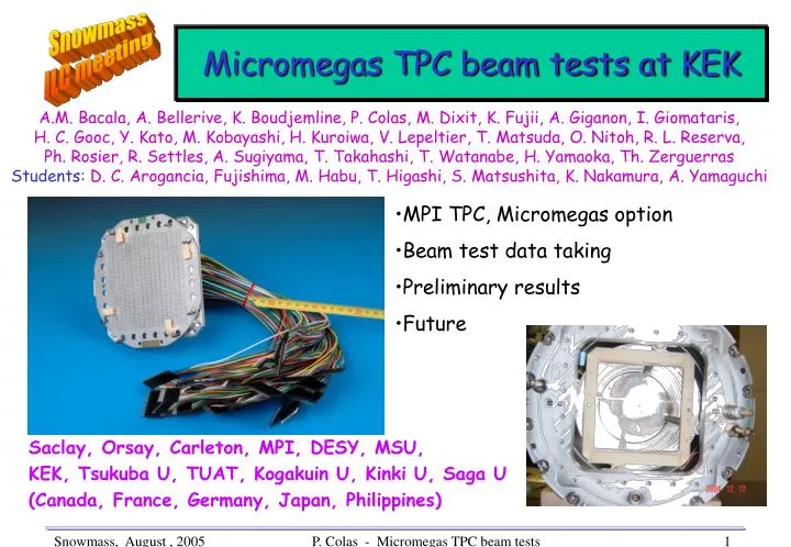
Snowmass ILC meeting Micromegas TPC beam tests at KEK A.M. Bacala, A. Bellerive, K. Boudjemline,P. Colas, M. Dixit,K. Fujii,A. Giganon, I. Giomataris, H. C. Gooc, Y. Kato, M. Kobayashi,H. Kuroiwa,V. Lepeltier, T. Matsuda,O. Nitoh,R. L. Reserva, Ph. Rosier,R. Settles, A. Sugiyama, T. Takahashi, T. Watanabe, H. Yamaoka, Th. Zerguerras Students: D. C. Arogancia,Fujishima,M. Habu,T. Higashi, S. Matsushita, K. Nakamura, A. Yamaguchi • MPI TPC, Micromegas option • Beam test data taking • Preliminary results • Future Saclay, Orsay, Carleton, MPI, DESY, MSU, KEK, Tsukuba U, TUAT, Kogakuin U, Kinki U, Saga U (Canada, France, Germany, Japan, Philippines) P. Colas - Micromegas TPC beam tests
MPI TPC, Motivation • Initiated by Ron Settles. Comparison of several gas amplifiers using same Field Cage, Electronics, analysis • MWPC : Beam test in Jun, 2004 • GEM : Beam test in Apr, 2005 • Micromegas Beam test in Jun. 22~Jul. 1, 2005 P. Colas - Micromegas TPC beam tests
S1 s S2 Micromegas 50μm • Micromesh supported by 50-100μm - high insulating pillars • Multiplication takes place between the anode and the mesh • One stage • Direct detection of avalanche electrons • Small E×B effect • Fast signals • Self-suppression of positive ion feedback the ions return to the grid • Better potential spatial resolution • No wire angular effect P. Colas - Micromegas TPC beam tests
The MPI TPC at KEK • Drift length : 26 cm • Pads • 2,3×6,3 mm pitches • 32 pads×12 pad rows ⇒ 384 readout channels • pad plane : 10×10 cm • Readout • ALEPH TPC electronics 24 amplifiers, 16 channels each 500ns shaping time, charge sensitive sampled every 80 ns digitized by 6 TPDs P. Colas - Micromegas TPC beam tests
Experimental Setup • KEK-PS π2 beam line • mainly 4 GeV π- • Superconducting magnet (JACEE) • B = 0, 0.5 and 1T • Gas • Ar + isobutane (95:5) • Drift field : • mainly 220 V/cm P. Colas - Micromegas TPC beam tests
55Fe 6keV Escape 3keV Mesh readout Calibration with a 55Fe source installed inside the chamber. Mesh readout by a Multichannel Analyser. Used for monitoring the gain P. Colas - Micromegas TPC beam tests
55Fe 6keV Escape 3keV Cosmics P. Colas - Micromegas TPC beam tests
June 2005 tests in KEK December to May : design and build the Micromegas endplate, all from drawings and photographs of the GEM endplate. June 4th,5th : assemble, test, install in Cryo-hall. Detect a leak. Re-glue the pad plane June 6th : Re-assemble, test with 55Fe in Ar+5%isobutane, OK, connect pad electronics. See tracks! Take data overnight June 7th-10th : Take cosmic data June 21st : Set last resistor value for E field continuity. Move to beam hall June 22nd to 25th : setup DAQ (with 380 channels) during machine studies June 26th, O:OO : start beam DAQ. July 1st : end of beam, end-of-run party and analysis meeting… P. Colas - Micromegas TPC beam tests
B=0T P. Colas - Micromegas TPC beam tests
B=0.5 T P. Colas - Micromegas TPC beam tests
Charge Distribution 3 Edge effect 2 4 1 B = 1T, row by row 8 7 5 6 Aver. charge distribution, Row6, as a function of z 11 9 10 Edge effect 12 no significant attenuation P. Colas - Micromegas TPC beam tests
Method Drift velocity measurement Using a beam at 45 deg. Look at time distribution on one pad. Max time gives drift time over 26.08+-0.02 cm beam 1 cm scint. Central row cathode P. Colas - Micromegas TPC beam tests
Time distributions P. Colas - Micromegas TPC beam tests
Result • Avoid side pads where the field might not be nominal. • Padrow 6: 5.907 ms • Padrow 7: 5.911 ms • Padrow 8: 5.911 ms • Padrow 9: 5.901 ms • Average 5.907 +-30 ns • Trigger cable delay (measured): 310+-5 ns • Trig. Logic and start TPD (guess) : 20+-20 ns • Total time 6.237+- 0.050 ms • Velocity = 4.181+-0.034 (t meas)+-0.003 (length) cm/ms Vdrift (Ar+5%iso) = 4.181 +- 0.034 cm/ms In agreement with Magboltz : 4.173 +- 0.016 Gas composition P. Colas - Micromegas TPC beam tests
Pad Response Function Charge width for different z drift regions (B = 0T) anode Z → evaluated by the charge fraction (NQi = Qi/∑Q) on pad i, as a function of (Xpad - Xtrack) Width increases with drift distance (diffusion) cathode P. Colas - Micromegas TPC beam tests
Width of Pad Response Function as a function of z B = 0T Preliminary results B = 0.5T B = 1T Measured CD in good agreement with Magboltz Simulation P. Colas - Micromegas TPC beam tests
B = 0T X Resolution vs Z Neff = 37+-1 B = 0T Use 8 rows, fix Cd, and fit: Fit Simulation (s0 from fit) Neff = 28+-9 B = 0.5T Neff ~ 35, much smaller than the average number of electrons (63 for 6.3 mm) Neff = 24+-6 B = 1T Preliminary results P. Colas - Micromegas TPC beam tests
z Resolution as a function of z B = 0T • σz ⋍ 500μm at 0.5T Preliminary results B = 0.5T B = 1T As expected, Unlike σX, σZ has no significant B-dependence P. Colas - Micromegas TPC beam tests
X Residual Mean and r.m.s. vs PadRows Distortions Mean B = 0T B = 0.5T B = 1T r.m.s. B = 0T B = 0.5T B = 1T P. Colas - Micromegas TPC beam tests
Conclusions • Micromegas tests went very smoothly (first ‘pad partout’ Micromegas TPC) • Provided a lot of accurate and clean data on diffusion, resolution, etc... • Much work remains for understanding s0, Neff, etc • Next step (October) : study the effect of a resistive foil on resolution, with 2 setups • The same, with a resistive foil added • The Carleton TPC, with a new 128 pad endplate and special electronics. • Very nice beginning of a world-wide collaboration P. Colas - Micromegas TPC beam tests