Download
1 / 42
490 likes | 941 Views
Chapter 23 Machining Processes Used to Produce Various Shapes. Alexandra Schönning, Ph.D. Mechanical Engineering University of North Florida Figures by Manufacturing Engineering and Technology Kalpakijan and Schmid. Introduction. What is milling?

E N D
Chapter 23 Machining Processes Used to Produce Various Shapes Alexandra Schönning, Ph.D. Mechanical Engineering University of North Florida Figures by Manufacturing Engineering and Technology Kalpakijan and Schmid
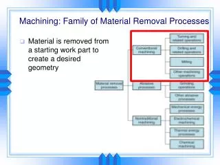
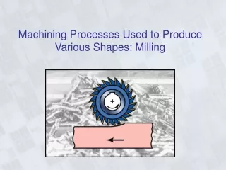
Introduction • What is milling? • A manufacturing process in which a rotating, multitooth cutter removes material while traveling along various axes with respect to the workpiece. • Other processes will be discussed, such as • Planing, shaping, broaching, sawing, filing, and gear manufacturing.
Milling operations • Slab milling (Figure a) • Arbor, cutter • Face milling (Figure b) • Spindle and cutter • End milling (Figure c) • Spindle, shank, end mill Figure 23.3 A typical part that can be produced on a milling machine equipped with computer controls. Such parts can be made efficiently and repetitively on computer numerical control (CNC) machines, without the need for refixturing or reclamping the part.
Slab Milling • Also called peripheral milling • The axis of cutter rotation is parallel to the workpiece surface to be machined • The cutter has a teeth along its circumference where each tooth acts as a single point cutting tool • Conventional vs. Climb milling • Conventional milling • Also called up-milling: the rotation of the cutter is such that it first engages the workpiece at the bottom. • The cut is not a function of the surface characteristics • Common method of milling. • Proper clamping is necessary to prevent the upward rotation of the cutter. • Climb milling • Also called down-milling: the rotation is such that the cutter first engages the workpiece at the top. • Cutting forces holds the workpiece in place. However, a rigid setup is important since there are high impact forces.
Conventional and Climb Milling Figure 23.4 (a) Schematic illustration of conventional milling and climb milling. (b) Slab milling operation, showing depth of cut, d, feed per tooth, f, chip depth of cut, tc, and workpiece speed, v. (c) Schematic illustration of cutter travel distance lcto reach full depth of cut.
The velocity at the point of contact The chip thickness can be found Feed per tooth Cutting time Material Removal Rate Definitions of symbols Definition of Symbols tc: chip thickness f: feed per tooth of cutter D: depth of cut N: angular speed in rpm n: number of teeth on cutter periphery v: linear speed (feed rate) t: cutting time L: length of the workpiece Lc: extent of the cutter's first contact with the workpiece (illustration on next page) w: width of cut Milling Parameters N = angular speed in rpm. This version of the formula is used in the book. It includes the unit conversion from rpm to radiance per minute. The units of the velocity are distance/min. As tc gets larger the forces on the cutter tooth increases It is assumed that lc<<l
Illustration of Lc Lc: extent of the cutter's first contact with the workpiece Lc
A slab milling operation is being carried out on a 12-in long, 4 in wide annealed mild steel block at a feed f=0.01 in/tooth and a depth of cut d=1/8 in. The cutter is D=2in in diameter, and has 20 straight teeth, rotates at N = 100rpm, and is wider than the block to be machined. Calculate the material Removal rate, estimate the power and torque required for this operation, and calculate the cutting time. Given: w=4in L=12 in f=0.01 in/tooth d=1/8 in D=2 in n = 20 teeth N = 100 rpm Cutter width > block width Specific energy: 1.1 hp*min/in3 Table 20:2 (annealed mild steel) Find Material Removal Rate Power Torque Cutting time Example
Cutter is mounted on a spindle having an external axis of rotation perpendicular to the workpiece surface Workpiece moves along a straight path at a linear speed, v. Direction of cutter Conventional milling (Fig. c) up-milling Climb milling (Fig. b) down-milling Leaves feed marks on the machined surface Terminology in figure Lead angles: 0-45o. Low angle low vertical force Face Milling Figure 23.8 Terminology for a face-milling cutter.
Face Milling v w d Figure 23.6 A face-milling cutter with indexable inserts. Source: Courtesy of Ingersoll Cutting Tool Company.
Cutter and Insert Position in Face Milling Figure 23.10 (a) Relative position of the cutter and insert as it first engages the workpiece in face milling, (b) insert positions towards the end of the cut, and (c) examples of exit angles of insert, showing desirable (positive or negative angle) and undesirable (zero angle) positions. In all figures, the cutter spindle is perpendicular to the page. Third example in figure c: the insert exits the workpiece suddenly as opposed to exiting with an angle.
End milling • The cutter, called an end mill, rotates about an axis perpendicular to the workpiece surface (typically – can be at an angle) • Ball nose: A type of end mill in which the bottom surface is rounded • Used in the production of curved surfaces for dies and molds
Other Milling Operations and Cutters • Straddle milling: two or more cutters are mounted on an arbor and are used to machine two parallel surfaces on the workpiece • Easier to keep tolerances than if milling one surface at a time • Form milling: produces curved profiles. Also used in machining gear teeth. • Circular cutters can be used for slotting and slitting. • Slitting saws are typically < 5mm. • T-slot cutters: used to mill T-slots which are used in clamping workpieces to the work table. (figure next page)
T-slot cutter Note order of cuts: 1st: cut slott so the T-cutter can move 2nd: finish the T-slot Shell milling Has a hollow inside. Mounted on a shank. Allows the same shank to be used for different size cutters Other Milling Operations and Cutters Figure 23.12 (a) T-slot cutting with a milling cutter. (b) A shell mill.
Tool holders • Milling cutters are classified as • Arbor cutters • Mounted on an arbor • Used in slab, face, straddle, and form milling • Shank cutters • The cutter and the shank are one piece. • Examples include end mills • Straight shanks • Mounted collet chucks or special end mill holder • Tapered shanks • Tapered for better clamping. • Common on larger end mills • Mounted in tapered tool holders
Arbor Figure 23.13 Mounting a milling cutter on an arbor for use on a horizontal milling machine.
Milling Process Capabilities • Process capabilities include • Surface finish, dimensional tolerance, production rate, and cost consideration • Feed rate (typical): 0.1 mm/tooth – 0.5 mm/tooth • Depth of cut (typical): 1-8 mm • Cutting speeds (varies much): 30m/min to 3000m/min
Capacities and Maximum Workpiece Dimensions for Machine Tools
Surface Features and Corner Defects Figure 23.14 Surface features and corner defects in face milling operations; see also Fig. 23.7. For troubleshooting, see Table 23.5. Source: Kennametal Inc.
Design and Operating Guidelines for Milling • Similar to the guidelines for turning • Use standard milling cutters • Chamfers should be used instead of radii because of the difficulty of smoothly matching various intersecting surfaces • Internal cavities and pockets with sharp corners should be avoided since cutters have a finite radius • Workpieces should be sufficiently rigid to minimize any defects resulting from clamping and cutting forces. • Minimizing vibrations • Cutters should be mounted close to spindle to reduce tool deflection • Tool holders and fixtures should be as rigid as possible • If vibration occurs • Modify tool shape and/or process conditions • Used a cutter with fewer teeth or with random tooth spacing
Column-and-knee type machines Most common The spindle may be horizontal or vertical Machine consists of A work table: on which the workpiece is clamped. A saddle: supports the table and moves in a perpendicular direction A knee: supports the saddle and allows for vertical movement (depth of cut) An overarm: in horizontal machines. It can accommodate different arbor lengths A head: contains a spindle and cutter holder Plain miling machines: 3 axes Universal column-and-knee milling machines: 4th axes (rotational) Milling Machines Horizontal spindle vertical spindle
Other types of milling machines • Bed-typed milling • A bed is used instead of the knee. No vertical movement is possible. • The work table is mounted directly on the bed. • Used in high production runs for simple parts. Figure 23.17 Schematic illustration of a bed-type milling machine. Note the single vertical-spindle cutter and two horizontal spindle cutters. Source: ASM International.
Planing and shaping • Cutting operation by which flat surfaces, grooves, and notches are produced along the length of the workpiece. • Typically performed on large workpieces. The workplane is mounted on a table that travels along a straight path • A horizontal cross-rail can be moved vertically • Shaping: similar to planing but for smaller parts • Used to machine notches, keyways, and dies Figure 23.20 Typical parts that can be made on a planer.
What is a broach? A long multitooth cutting tool. Used for what? To machine internal or external surfaces, such as holes of different sections, the teeth of internal gears, multiple spline holes, and flat surfaces. Terminology and geometry: Rake angle typically from 0-20 degrees. Clearance angle typically from 0-4 degrees. Pitch = k*sqrt(L) (to find appropriate pitch) k = 1.76 when L is in mm k = 0.35 when L is in inches L = length of surface to be cut At least two or more teeth should be in contact. Different type of broaches exist Surface broaches: Slab broaches (for cutting flat surfaces), slot, contour, dovetail, straddle, pot (precision of external shapes) Internal broaches include hole, keyway, internal gear, and rifling Broaching and Broaching Machines Figure 23.22 (a) Cutting action of a broach, showing various features. (b) Terminology for a broach.
Broaching and Broaching Machines • Turn broaching • The workpiece is rotated between centers, and the broach passes tangentially across the bearing surfaces and remove material • Broaching Machines • Either pull or push the broaches and are made either horizontal or vertical. • Forces required depend on workpiece material, total depth and width of cut, and cutting speed. • Broaching process parameters • Cutting speeds range from 1.5m/min for high strength alloys to 15m/min for Aluminum alloys • Ceramic inserts may be used for finishing operations • Design Considerations for Broaching • Parts should be designed such that they can be clamped securely • Blind holes, sharp corners, dovetail splines, and large flat surfaces should be avoided • Chamfers are preferred over round corners
(a) (c) (b) Chipbreakers and a Broaching Machine Figure 23.23 Chipbreaker features on (a) a flat broach and (b) a round broach. (c) Vertical broaching machine. Source: Ty Miles, Inc.
Internal Broach and Turn Broaching Figure 23.24 Terminology for a pull-type internal broach used for enlarging long holes. Figure 23.25 Turn broaching of a crankshaft. The crankshaft rotates while the broaches pass tangentially across the crankshaft’s bearing surfaces. Source: Courtesy of Ingersoll Cutting Tool Company.
Sawing • A saw consists of a blade with a series of small teeth. • The width of the cut is called the kerf and is typically thin resulting in little waste material. • At least two or three teeth should be engaged for the blade to prevent snagging (catching the saw tooth on the workpiece). • The thinner the stock, the finer the saw teeth should be, and the greater the number per unit length. Figure 23.27 Examples of various sawing operations. Source: DoALL Company.
Sawing • Types of saw teeth Figure 23.28 (a) Terminology for saw teeth. (b) Types of tooth set on saw teeth, staggered to provide clearance for the saw blade to prevent binding during sawing.
Sawing • Types of saws • Hacksaw: Straight blades, reciprocating motion. Cutting only takes place during one of the two reciprocating strokes. • Circular saw: Also called cold saw. Used for… • Band saw: continuous long, flexible blades and have a continuous cutting action. (both ways) runt band • Diamond edge blades and diamond wire saws: high strength wire is coated with diamond particles. Used for cutting hard metallic, nonmetallic, and composite materials. • Friction sawing • A steel blade, or disk, rubs against the workpiece at speeds up to 7600m/min. • The frictional energy is converted into heat, which softens a narrow zone in the workpiece. • Used to cut hard ferrous metals and reinforced plastics. • Commonly used to remove flash form castings
Filing and Finishing • Filing: Small scale removal of material from a surface, corner, or hole, including removal of burrs. • Shapes: flat, round, half round, and triangular • Rotary files and burs: • Used for removing material in die making, deburring, scale removal from surfaces, and producing chamfers on parts Figure 23.30 Types of burs. Source: The Copper Group.
How are gears manufactured? Casting, forging, extrusion, drawing, thread rolling, powder metallurgy, blanking sheet metal, injection molding (non metallic), casting (non metallic), and machining. Gears can be machined by Form cutting (future slides) Gear generating (future slides) Gear terminology Gear Manufacturing by Machining Figure 23.31 Nomenclature for an involute spur gear.
The gear-tooth shape us reproduced by cutting the gear blank around its periphery. After each tooth is cut, the cutter is withdrawn, and the gear blank is rotated (indexed). Form cutting can be done on milling machines, with the cutter mounted on an arbor and the gear blank mounted in a dividing head. Limitation: Form cutting can only produce gear teeth that have constant width (spur and helical but not beveled gears. Form Cutting Figure 23.32 (a) Producing gear teeth on a blank by from cutting. (b) Schematic illustration of gear generating with a pinion-shaped gear cutter. (c) Schematic illustration of gear generating in a gear shaper using a pinion-shaped cutter. Note that the cutter reciprocates vertically. (d) Gear generating with rack-shaped cutter.
The cutting tools in gear generating may be one of the following: A pinion-shaped cutter The cutter is one of the gears in a conjugate pair. The other gear is the blank. A rack-shaped straight cutter The generating tool is a segment of a rack which reciprocates parallel to the axis of the gear blank. Gear Generating
Gear Generating • Hob: A worm or screw made into a gear-generating tool. • It consists of slots that will be used to cut the teeth. • The angle between the axis of the hob and the gear are about 90 degrees apart.
Cutting Bevel Gears Figure 23.34 (a) Cutting a straight bevel-gear blank with two cutters. (b) Cutting a spiral bevel gear with a single cutter. Source: ASM International.
Grinding Form Grinding The shape of the wheel is identical to the tooth spacing. (Figure A) Generating The grinding wheel acts as shown in Figure (b) Honing The tool is a plastic gear impregnated with fine abrasive particles. Improves surface finish. Lapping To further improve surface finish. Uses an abrasive compound Gear Finishing Procedures
Gear Manufacturers Association • AGMA: American Gear Manufacturers Association • Sets the standards for gears in the US