Download
1 / 36
370 likes | 562 Views
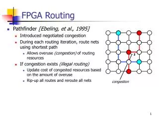
Multiple-FPGA System; SoC Verification using an array of FPGA ’ s. In-circuit Logic Emulator. Simulation Accelerator. Emulator. Emulator. C testbench. HDL testbench. Introduction. Hardware Emulation System

E N D
Multiple-FPGA System;SoC Verification using an array of FPGA’s
In-circuit Logic Emulator Simulation Accelerator Emulator Emulator C testbench HDL testbench Introduction • Hardware Emulation System • Device for verifying digital circuit design along with its target system prior to fabrication of chips • Merits • Fast verification of the logic design compared to software simulation • Real (physical) signal application/monitoring is possible.
Introduction • Why Emulation? • FPGA prototype allows design verification with real signals to and from the target environment, at a speed lot faster than software simulation. Setup time Minute Logic Simulation Accelerated Simulation Hour Logic Emulation Day Week Final Silicon Month Execution time Year Month Week Day Hour Minute
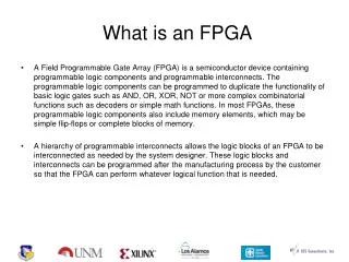
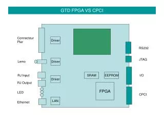
FPGA vs. Emulation System • FPGA • Developed in1980’s • Reconfigurable logic and routing architecture • The gate capacity of FPGA is smaller than that of the state-of-the–art ASIC design • Currently, gate count of FPGA with maximum gate capacity is about 20-30 M gates (For 8 M-gate FPGA, about 1.6M gates are for logic gates while the rest is memory.) • Emulation Systems • An array of FPGA’s or special processors are interconnected via. interconnection networks. • The whole target design must be partitioned into a set of sub-circuits, such that each can be contained in an FPGA.
Requirements of Hardware Emulator • Five Requirements • 1.Gate capacity • With the advent of SOC era, about 50-100M (Intel’s P4 is about 60M gates including cache memories) • 2.Speed • Emulation system should be faster than other verification environments Cycle/sec (Hz) 1MHz 10KHz 100Hz Hardware Emulator Software Simulation Coverfication w/ Emulator
Requirements of Hardware Emulator • 3.Debuggability • Today’s emulators provide 100% debugging capability. • 4.Expandible architecture • The architecture of emulator should be expandible to include more logic gates. • 5.Low Cost • Cost of current emulators is still very high. • Cost of Mercury from Quickturn $4M ~ $5M, with each FPGA board addition $0.2M
Basic architecture of Emulators • Multiple FPGA’s • Multiple FPGA’s can be connected to increase the gate capacity of emulation system. • Several interconnection architecture • Full Crossbar network, folded-Clos network • Time-multiplexed interconnect • Virtual wire • Embedded logic analyzer • Customized FPGA to extract internal values. • Local memory to save extracted values.
Partitioned circuits by commercial partitioning tools for several designs. Xilinx, Altera do not have many pins for partitioned circuits Pin limitation • Pin count vs. Gate count of partition • Many large designs yield far more pins than available from FPGA’s • Sparcle processor : Processor designed by MIT, LSI Logic and Sun for multiprocessor system at 1994. • Alewife CC : Cache controller designed at MIT
Interconnection Architectures • Mesh type interconnection • 2D mesh for FPGA interconnection • Crossbar network (Separated Interconnection) • One Full crossbar network • Partial crossbar network (folded-Clos) • Time-multiplexed • Dynamic FPID interconnect architecture • Time-multiplexed interconnect from Quickturn • Virtual Wire
Mesh Interconnection • Another 2-D mesh • (US patent 6389379, Axis, 2002) • FPGA’s on the same row/column are connected. • Only two “Hops” and “Jumps” are sufficient for any type of net. • Each FPGA resource is used for routing as well as logic mapping, which aggravates pin limitation problem. FPGA 11 FPGA 12 FPGA 13 FPGA 14 FPGA 21 FPGA 22 FPGA 23 FPGA 24 FPGA 31 FPGA 32 FPGA 33 FPGA 34 FPGA 41 FPGA 42 FPGA 43 FPGA 44
Crossbar Network • Full crossbar • Separates logic FPGA from interconnection device. • One full crossbar connects any net of any FPGA to any net of any FPGA after programming. • The size of full-crossbar grows exponentially as the number of FPGA’s increases FPGA 0 FPGA 1 FPGA 2 FPGA 3 A B C D A B C D A B C D A B C D Full Crossbar
Crossbar Network • Partial crossbar • (“An Efficient Logic Emulation System,” TVLSI, 1993) • I/O of each FPGA is divided into subsets. The pins of each crossbar chip are connected to the same subset of pins from each FPGA. • Still requires a large number of crossbars called FPID (Field Programmable Interconnection Device). FPGA 0 FPGA 1 FPGA 2 FPGA 3 A B C D A B C D A B C D A B C D C0 C1 C2 C3
Crossbar Network • What is FPIC? • “Field-Programmable Interconnect Component” • Reconfigurable interconnection chip. • Aptix.Inc incorporates FPIC for the interconnection. FPIC
Time-Multiplexed Interconnect • 1)Dynamic FPID; • Different interconnection among the same logic module set • Each FPID is time-multiplexed FPID (“Routability Improvement Using Dynamic Interconnect Architecture,” TVLSI 1998) 1 L L-th crossbar
Time-Multiplexed Interconnect • 2)Time-multiplexed interconnect from Quickturn • (US Patent 5960191, Quickturn, 1999) • Partial crossbar is used but connected pins are time-multiplexed. • Multiple pins are multiplexed with only 1/n pins are required if n-to-1 mux is used. D E F C G A B B F D A E C G MUX DEMUX MUX DEMUX MUX DEMUX MUX DEMUX DEMUX DEMUX MUX MUX MUX MUX DEMUX DEMUX B F F D A E C D A E B C G G Crossbar Crossbar MUX CHIP MUX CHIP
Time-Multiplexed Interconnect • “Mux Clock” samples signal A and signal B • “SYNC” disables sampling and synchronize sampling operation Signal A Signal B MUX Clock Divided Clock SYNC for user clock A B A B A B B A B A B A Composite Signal
Time-Multiplexed Interconnect • 3)Virtual Wire • (“Logic Emulation with Virtual Wires,” TCAD, 1997) • Several logic connections share the same physical wire. • Communication schedule is static and predicted (Analysis of logic circuit should be done before assigning phase to each circuit partition.) FPGA #1 FPGA #2 Simultaneous Logical outputs phase1 Logical outputs Logical inputs Virtual wire phase2 Logical inputs Mux Shift loops
Phase 1 Phase 2 Phase 3 Phase 4 Comb. logic CLK Enable Comb. logic Evaluation Communication Comb. logic Time-Multiplexed Interconnect • Phase assignment • At the end of the phase, the produced outputs are transferred to the other partition. Emulation Clock
Software for Multi-FPGA • Partitioning • Various partitioning algorithms were proposed. • Placing highly interconnected circuit into a single chip is desirable due to limited number of I/O pins. • Circuit paths that require short delay time should be inside one FPGA. • Routability vs. Performance trade-off. • Placement • Assign each partitioned circuit to one of FPGA’s
Software for Multi-FPGA • Routing • Global routing • Select routing switches (or crossbar) or additional FPGA’s the signal must pass through to get to the destination FPGA. • Detailed routing • Assign signals to actual traces on each FPGA • Time-multiplexed FPGA • The routing algorithm to meet the relevant precedence relations is necessary in Virtual Wire.
Run-Time Reconfiguration • Meeting the exploding gate capacity • With RTR, where time-multiplexed FPGA executes the whole circuits in time-domain slices, the gate capacity is greatly increased. • Run-time reconfiguration was proposed in mid-1990’s. • Run-time reconfiguration (RTR) • Technology to swap different configurations in the reconfigurable hardware • The configuration in different time slots should be assigned registers to communicate with the other configurations.
Reconfiguration Model • Single context • One full-chip configuration can be loaded at a time. • Sequential access for reconfiguration requires high overhead. (Configuration of FPGA takes 5ms~20ms for XILINX Virtex series) incoming configuration FPGA (Logic & Routing) FPGA (Logic & Routing) Configuration
Reconfiguration Model • Multi-context • Multiple planes of configuration information • Switching between several configurations is fast. • Xilinx XC4000E, Chameleon Inc.’s CS2000 RCP incoming configuration FPGA (Logic & Routing) FPGA (Logic & Routing) Configuration
Xilinx XC4000E micro-registers, which stores the result of each context are routed to the relevant logic block. Each logic element incl. LUT has multiple(8) configuration planes in SRAM
Reconfiguration Model • Partially Reconfigurable • Some part of the FPGA can reconfigured. Not entire array reconfiguration. • Reduction of configuration data. • Programming information can be large because of address information. • Xilinx 6200, Xilinx Virtex-II incoming configuration FPGA (Logic & Routing) FPGA (Logic & Routing) Configuration
Reconfiguration Model • Pipeline Reconfigurable • Partial reconfiguration occurs in increments of pipeline stages. • Primarily used in datapath style computations. Time Pipeline stages Configure 1 Execute 1 Execute 1 Configure 4 Execute 4 Execute 4 Configure 2 Execute 2 Execute 2 Configure 5 Execute 5 Configure 3 Execute 3 Execute 3 Configure 6
group 0 group 1 group 2 Configuration Scheduling Lifetime of each wire Configuration time group0 wire 4,6 wire 4,7 wire 2,5 wire 5,6 1 2 3 group1 4 5 7 6 group2 The precedence relation should be preserved when the circuit is partitioned.
Fast Configuration • Problem of run-time reconfiguration • Run-time reconfigurable systems involve reconfiguration during program execution. • The reconfiguration time can somewhat offset the performance improvement achieved by hardware acceleration. • Configuration time • DISC II system • “Dynamic Instruction Set Computer’’ implemented on partially reconfigurable FPGA’s. • M. J. Wirthlin, and B. L. Hutchings, “Sequencing run-time reconfigured hardware with software”, ACM/SIGDA International Symposium on FPGAs, pp. 122-128, 1996. • 25%-71% of execution time is spent on reconfiguration. • UCLA ATR : • “Automatic Target Recognition” implemented with RTR. • W. H. Mangione-smith et al., “Seeking solutions in configurable computing”, IEEE Computer, vol. 30, No. 12, pp. 38-43, 1997. • Over 98.5% is reconfiguration time.
Fast Configuration • Configuration Prefetching • Used in cosimulation environment. • Configuration time and host execution time are overlapped. Hides the configuration time. • Configuration Compression • Used in cosimulation environment. • The communication time between host processor and FPGA can be minimized by compressing configuration data. • Xilinx XC6200 : One configuration data can configure several configuration registers.
Fast Configuration • Configuration Caching • The communication time to send configuration data from host to target FPGA is the main reason for slow configuration. • Cache to save configuration data can be located near the FPGA to reduce the communication time.
Commercial Emulators • Axis • XtremeTM • Simulation/Emulation/Acceleration • System with multiple PCI cards with multi-FPGA. • Interconnection between FPGAs is mesh interconnection. • RCC technology is used for simulating designs.
Commercial Emulators • RCC (ReConfigurable Computing) • Consists of many computing elements (Small compact processor dedicated to perform one function) ALTERA FLEX10K ALTERA FLEX10K ALTERA FLEX10K ALTERA FLEX10K always @(posedge clk) nr_bus = inst; if(bus_active).. ALTERA FLEX10K ALTERA FLEX10K ALTERA FLEX10K ALTERA FLEX10K inv inv1(a, b); nand(a, b, c); … PCI Interface SIMD Controller initial begin #monitor(…); $my_pile(…); UltraSPARCII Workstation
Commercial Emulators • RTL language compiler • RCC RTL compiler compiles HDL to RCC elements. • The user needs not to debug in gate-level. Traditional RTL verification flow Emulation engine Debugger RTL Design Synthesis Gate-level Design RCC RTL compiler RCC array Debugger RTL Design Computing elements Compiler
Commercial Emulators • Debugging • HotSwapping between software simulation state and RCC states. • HotSwapping enables the user to probe the RTL constructs from the simulation time where the user wants to view.
Commercial Emulators • Quickturn • PalladiumTM • Components • 1. Custom ASIC matrix to emulate circuits • 2. FPGA array • 3. Embedded logic analyzer • 4. External I/O interface • Simulation acceleration modes • Synthesized testbench : Testbenches are synthesized into the emulator. • Transaction-based simulation : Decoupled simulator and accelerator • Accelerated cosimulation(cycle-level transaction) : Simulator and accelerator run in lock-step.
Summary • Multi-FPGA Architecture • Mesh • Crossbar • VirtualWire, Time-multiplexed interconnect • Problems • Nets with multiple ports may not be routable in the previous architectures. • The usage of FPGA logic in mesh topology is small (under 30%) • Crossbar architecture needs additional hardware for interconnection larger cost for emulators • RTR Architecture