Download

1 / 32
340 likes | 580 Views
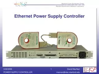
Ethernet Power Supply Controller . Ethernet Power Supply Controller (EPSC). The EPSC was intended as a replacement for the PEP 2 Bitbus Power Supply Control chassis The intent was to provide as much commonality as possible with the Bitbus controller

E N D
Ethernet Power Supply Controller(EPSC) • The EPSC was intended as a replacement for the PEP 2 Bitbus Power Supply Control chassis • The intent was to provide as much commonality as possible with the Bitbus controller • The performance was to be equal or better then the Bitbus chassis • Should not cost more then Bitbus controller
The main components to be changed • The DAC used in the Bitbus chassis is obsolete and a new DAC was required. • The Bitbus network is obsolete and it is desirable to convert to Ethernet (10/100 Mb/sec over UTP) • The FPGAs are at end of life and are not good choices for new designs • The 8044 processor is obsolete • Use standard +/-15VDC power supply
The main features to preserve • Size of controller (1U in 19 inch rack) • Power Supply, Transductor, and Interlock connector types and interfaces • Use Bitbus Daughter Boards • Support Bitbus command set • Use existing Bitbus local control board • Support for redundant transductor • All interlocks handled by FPGA, not software • Ability to reset processor without turning off power supply
Desirable improvements • Improved speed and resolution of ADC • Internal Fan to allow true 1U stacking • Air Filter and closed chassis to minimize dirt • Provide option of analog or digital regulation • Magnet Interlock circuit to locate faulted klixons in magnet strings • Extended analog readbacks
Power supply controller functions • Precision current regulation (using PS as voltage source) • Setting and ramping of currents • Readback of current, voltage, and ground current • Ground fault protection • Hardware magnet and power supply protection (no software) • Fault latching and reporting • Simple low cost serial communication to central control
Interface to Standard Components • Power Supplies of many ratings, types and from different vendors • Board range of current transducers (transductors) • Standard cables (Cat 5 UTP and D-sub computer cables)
Current Input Daughter Board Voltage Input Daughter Board 150, 300, and 600 amp Danfysik Transductors > 600 amp Transductors
Local Control Board Allows Local control of Power Supply Voltage or Current Regulation Analog Test Points Same as Bitbus Local Controller
Processor board • Uses 32 bit Motorola Coldfire processor • 512K of flash program memory • 8M of SDRAM memory • Provides Ethernet interface and 3 UARTS • C Libraries and Compiler • Boot loader over Ethernet • TCP/IP stack • Real time operating system (uCOS)
Sigma Delta ADCs • Two Burr Brown ADS1255 • 24 Bit Sigma-Delta ADC • 6 PPM linearity (corrected to 2 PPM) • Input amplifier provides +/- 12V range • 20 bit effective resolutuion of 10V range at 60 samples/sec • Gain set by oven stabilized zener (0.25 PPM/C) • Gain and offset readings interleaved with data
DAC (PWM) • 8 bit PWM • 32 MHZ clock • 117 KHZ period (274 clocks) • 9 clock minimum ON/OFF period • 24 bit input latch • Forth order digital filter • Output regulated using ADC1
Analog and Digital Regulation • 4 modes of operation • Error Amplifier with DAC reference • Error Amplifier with Local Control reference • Direct PS control with Local Control • Direct PS control with DAC, digital regulation using processor and ADC1
Klixon Fault Location Circuit • Allows klixon fault location in strings of up to 40 klixons • Two circuits per controller • Three wire interface, no active components in radiation areas • Controller senses current in interlock chain after a fault, converts to conductance to locate faulted klixon.
Fan Speed Control • Fan voltage programmable from 5V to 13V • Speed changes from 3000 to 9000 RPM • Voltage at minimum below 90 ° F • Voltage at maximum above 105 ° F • Fan filter on front panel of controller • Fan RPM calculated from current pulses • Air ducted below PC board
Current Status • 2 Prototype units built • 4 Pre-Production units built • 40 Production Units under construction • 30 units for SSRL • 7 units for LCLS injection
Comparison of Bitbus and EPSC Controller Performance Bitbus EPSC Unit Parameter 2 30/60 ADC readings per second 12 3 uV RMS ADC noise (0.1 to 10 Hz) 18 20 Bits Effective number of bits (10V FS) 21 24 Bits DAC resolution * 2 uV RMS DAC noise (0.1 to 10 Hz) * 2 PPM max DAC Linearity 0-10V 0.25 0.25 PPM/°C max ADC temperature stability max 1.0 1.0 PPM/°C typ Daughter card temperature stability typ