Download
1 / 9
90 likes | 95 Views
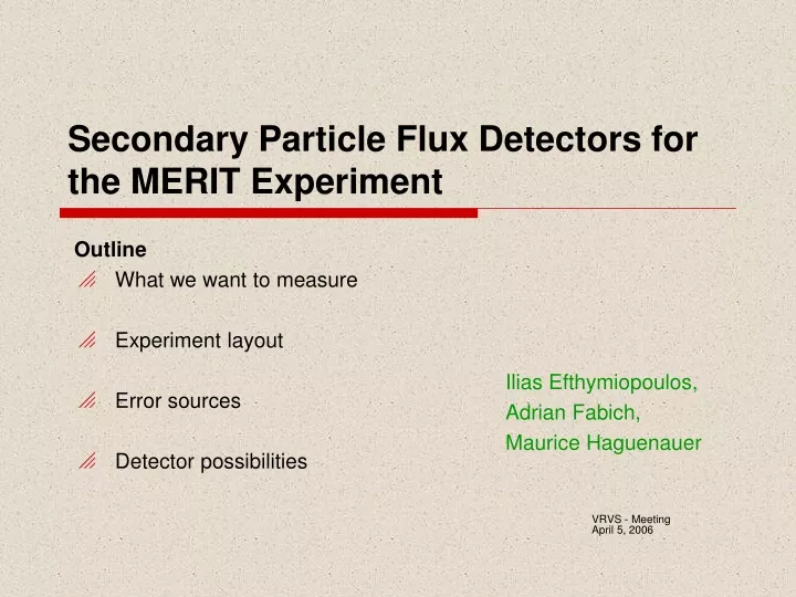
Secondary Particle Flux Detectors for the MERIT Experiment. Outline What we want to measure Experiment layout Error sources Detector possibilities. Ilias Efthymiopoulos, Adrian Fabich, Maurice Haguenauer. VRVS - Meeting April 5, 2006. n=1. dn. What we want to measure.

E N D
Secondary Particle Flux Detectors for the MERIT Experiment Outline What we want to measure Experiment layout Error sources Detector possibilities Ilias Efthymiopoulos, Adrian Fabich, Maurice Haguenauer VRVS - Meeting April 5, 2006
n=1 dn What we want to measure Questions to answer : • Is there any particle yield reduction at high beam intensities? • Simulate high intensities with pump/probe method • Is there any cavitation developed that reduces the effective target length? • We know that cavitation occurs but how it develops in a 15T magnetic field? • The times involved are “slow”, c~1.5km/sec not PUMP: 6 bunches, 15*1012 protons Target parameters - reminder: • 1-cm diameter Hg jet, v 20m/s • Pump-probe method to simulate target excitation and 50 Hz operation as in n-fact • Proton beam: • 24 GeV/c from the PS (single turn) • 14 GeV/c (multiple turns, Dt>1 us) • Bunch length: • 50ns (base), spaced every 131ns PROBE: 2 bunches, 5*1012 protons I. Efthymiopoulos - CERN
The Experimental Layout Beam profile measurement Beam Dump Solenoid / target Hg-loop system I. Efthymiopoulos - CERN
MERIT - Particle Detection System Strategy • No need to measure sub-bunch structure, i.e. integrate answer for each bunch • Relative measurement between bunches • i.e. compare 6 measurements (pump) to two measurements (probe) • Aim to an overall precision of few % • 5% should be possible, even 10% would be sufficient as answer Detector requirements and constraints • Integrate particle counting within 60 ns (50ns pulse + margin) • Readout within 60 ns or storage (memory) • High particle fluxes : ~107 particles/cm2/bunch • Radiation • Magnetic field I. Efthymiopoulos - CERN
MERIT - Particle Detection System Measurement precision: Relative measurement between bunches two sources of error • The knowledge of the beam • Beam intensity (bunch-to-bunch) • Beam direction ({x, y} at target, angle) • Beam longitudinal length (bunch shape, out of bunch particles) • The precision of our detectors • Number of particles to integrate, S/N • Stability over time • Acceptance vs target configuration I. Efthymiopoulos - CERN
Input beam definition Intensity measurement - Bunch-Current-Transformers (BCTs) • Inside the PS ring just before extraction • possible to measure bunch per bunch ; 2-5% precision can be achieved • At TT2 transfer line, right after extraction • measure total intensity of the extracted beam • Measurement error: • BCT precision, assuming same losses for pump and probe bunches in the TT2 line • Calibrate the two BCTs using a single turn extraction at 14 and 24 GeV/c • Kicker current setting would contribute for multiple turn extraction • Could be measured/corrected afterwards • Test of kicker repeatability – during 2006 MDs ??? • Beam simulations: • particle losses in TT2 vs kicker setting • beam location at the MERIT target vs kicker setting I. Efthymiopoulos - CERN
Input beam definition Beam spot and angle measurement • Use beam profile monitors installed upstream of the experiment • Baseline: MTV screens • <1mm precision • 3 m distance 160micro-rad precision • Provide {x,y} location • Alignment: <0.3mm relative between target and MTVs (6 m) • Alternative option: • BPMs of LHC Longitudinal bunch shape • Measured online inside the PS ring • Gives also the number of particles out of bunch (<% effect) All measurement data can be fetched from the PS control system logs I. Efthymiopoulos - CERN
Particle fluxes • MARS simulation results • Detector locations: • at large angle around Z=0 cm • at large angle downstream • Cherenkov signal of fast protons • Small detectors • scintillators or silicon diodes • Behind the dump in straight line • Muon detector (scintillator) • Particle fluxes: • ~107 particles/cm2/1012pot • 33 cm2 detector • 108 particles /bunch S.Striganov – 18.10.2005 I. Efthymiopoulos - CERN
The Experimental Layout Beam profile measurement Beam Dump Solenoid / target Hg-loop system Threshold Cherenkov counter • 1m long pipe, 156mm OD • Filled with N2 gas, set to pion threshold at >5 GeV/c • Pb sheets in front to reduce electron rate I. Efthymiopoulos - CERN