Download
1 / 28
280 likes | 359 Views
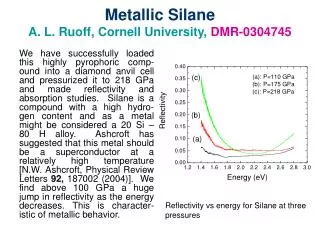
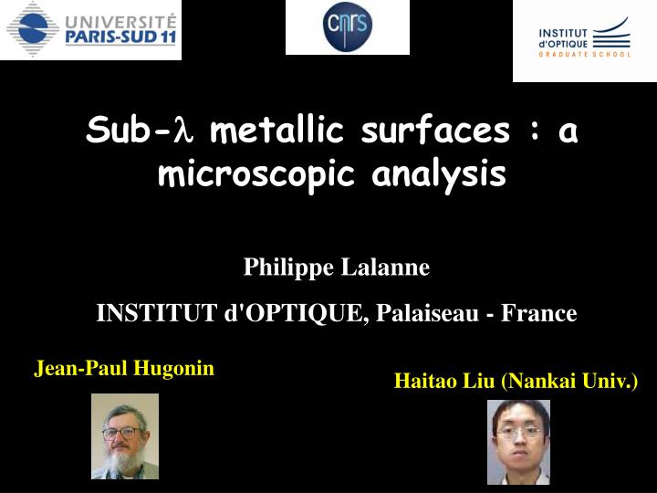
Sub- l metallic surfaces : a microscopic analysis. La TEO a été decouverte il y a une dixaine d'annees. Elle est rapidement devenue un phénomène emblématique de la plasmonique qui a suscites des querelles, des polémiques, des passions souvent trop fortes pour expliquer. Philippe Lalanne

E N D
Sub-l metallic surfaces : a microscopic analysis La TEO a été decouverte il y a une dixaine d'annees. Elle est rapidement devenue un phénomène emblématique de la plasmonique qui a suscites des querelles, des polémiques, des passions souvent trop fortes pour expliquer. Philippe Lalanne INSTITUT d'OPTIQUE, Palaiseau - France Jean-Paul Hugonin Haitao Liu (Nankai Univ.)
edem ed+em ( ) w 1/2 kSP= c Surface plasmon polariton z z exp(-k1z) Dielectric x x exp(-k2z) Metal SPPs are localized electromagnetic modes/ charge density oscillations at the interfaces, which exponentially decay on both sides
Re(w/c) w=ck wp/2 k Surface plasmon polariton exp(-z/d1) d1=le1/2/2p >> l kSP z kSP Dielectric x exp(-z/d2) d2=le-1/2/2pcte Drude model : |e| l2
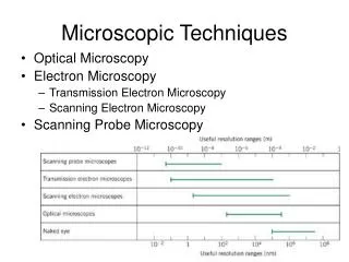
1.The emblematic example of the EOT -extraordinary optical transmission (EOT) -limitation of classical "macroscopic" grating theories -a microscopic pure-SPP model of the EOT 2.SPP generation by 1D sub-l indentation -rigorous calculation (orthogonality relationship) -slit example -scaling law with the wavelength 3.The quasi-cylindrical wave -definition & properties -scaling law with the wavelength 4.Multiple Scattering of SPPs & quasi-CWs -definition of scattering coefficients for the quasi-CW
The extraordinary optical transmission De quoi s'agit t'il? Avant tout, il s'agit de la transmission a travers une matrice de petits trous (plus petits que ld) qui presente un peak de transmission et un minimum a une longueur d'onde plus petite. T. W. Ebbesen, H.J. Lezec, H.F. Ghaemi, T. Thio and P.A. Wolff, Nature 391, 667 (1998).
transmittance (w,k//) 1/l (µm-1) SPP of the flat interface minimum EOT peak Two branches k//
The extraordinary optical transmission 2 T (%) 1 0 640 720 800 l (nm) Black : experiment red : Fano fit C. Genet et al. Opt. Comm. 225, 331 (2003)
The extraordinary optical transmission -The effect is accompagnied by a field surprising funneling of light at the resonance transmission and of a strong squeezing of light in small volumes. Hhow do we understand that for specific wavelength, no light goes through, and for some other one, more light is transmitted than the light directly impinging onto the hole apertures? The initial vision proposed by ebessen and his coworkers to explain the EOT is the excitation of SPPs on the metallic surface. Since 10 years, there have been a considerable amount of works to explain the EOT, experimental numerical, and theoretical works. I just peak out two beautiful contributions leading to an anlytical formula for the transmission. ? T. W. Ebbesen, H.J. Lezec, H.F. Ghaemi, T. Thio and P.A. Wolff, Nature 391, 667 (1998).
The extraordinary optical transmission = a grating scattering problem
What is learnt from grating theory? Phil. Mag. 4, 396-402 (1902).
Wire grid polarizer Inductive-capacitive grids Nearly 100% of the incident energy is transmitted at resonance frequencies for TM polarization • Hertz (1888) first used a wire grid polarizer for testing the newly discovered radio wave. • J.T. Adams and L.C. Botten J. Opt. (Paris) 10, 109–17 (1979). • R. Ulrich, K. F. Renk, and L. Genzel, IEEE Trans. Microwave Theory Tech. 11, 363 (1963). • C. Compton, R. D. McPhedran, G. H. Derrick, and L. C. Botten, Infrared Phys. 23, 239 (1983).
Poles and zeros of the scattering matrix l-lz tF |tF|2 l-lp rF 0.2 The Fano-type formula is very elegant but does not explain why the pole exist, why it is close or not to the real axis. 0.1 0 700 750 800 l (nm) -Global analysis. -Why does the pole exist? Why does the zero exist? Why are they close or not to the real axis? tF E. Popov et al., PRB 62, 16100 (2000).
tA2 exp(ik0nd) tF= 1- rA2 exp(2ik0nd) 30 20 10 0 650 700 750 800 The surface-mode interpretation you assume that inside the grating, the light is transmitted from the top to the bottom interfaces only via the fundamental evanescent mode of the hole array. (Doing that, one obtains a FP formula, where the exponential factor is small because the effective index is imaginary. The resonant transmission is then explained as a resonance of the rA and tA coefficients.) Doing that you obtain a FP-like analytical expression of the transmission coefficient. This is great but not completely satisfactory since the resonance of the transmission coefficient is explained through the resonance of another scattering coefficient. This is something like shifting the real problem. Le probleme avec cette interpretation, c'est que peu de temps apres de nouvelles manips ont montre que la TEO pouvait etre reproduite a des ld bcp plus grandes, ds l'infrarouge puis ds le domaine THz. La le metal peut etre considerer comme quasi parfait et l'interpretation à base de plasmon de surface Resonance-assisted tunneling tA rA L. Martín-Moreno, F. Garcia-Vidal & J. Pendry, Phys. Rev. Lett. 86, 1114 (2001). tF rA l (nm)
The surface-mode interpretation 1/l SPP of the flat interface Black board : flat SPP versus surface mode of the corrugated surface |Hy| Mode of the perforated interface = pole of rA or tA Hybrid character k// P. Lalanne, J.C. Rodier and J.P. Hugonin , J. Opt. A 7, 422 (2005).
tA2 exp(ik0nd) tF= 1- rA2 exp(2ik0nd) 30 20 10 0 650 700 750 800 The surface-mode interpretation Resonance-assisted tunneling tA rA L. Martín-Moreno, F. Garcia-Vidal & J. Pendry, Phys. Rev. Lett. 86, 1114 (2001). Reinforce the initial SPP vision tF rA reinforcement of the initial vision of a SPP assisted effect l (nm)
The surface-mode also exists as l perfect conductor Theory : J. Pendry, L. Martín-Moreno & F. Garcia-Vidal, Science 305, 847 (2004). Experimental verification : P. Hibbins et al., Science 308, 670 (2004). "SPOOF" SPP
tA2 exp(ik0nd) tF= 1- rA2 exp(2ik0nd) Weaknesses of classical grating theories -The resonance of tF is explained by the resonance of another scattering coefficients. This is unsatisfactory. -In reallity, nothing is known about the waves that are launched inbetween the hole and that are responsible for the EOT Resonance-assisted tunneling rA L. Martín-Moreno, F. Garcia-Vidal & J. Pendry, Phys. Rev. Lett. 86, 1114 (2001). 30 rA -The resonance of tF is explained by the resonance of another scattering coefficients. -In reality, nothing is known about the waves that are launched in between the hole and that are responsible for the EOT 20 10 0 650 700 750 800 l (nm)
l-lz r l-lp R(q0,l0)=0 l/30 M. C. Hutley and D. Maystre, “Total absorption of light by a diffraction grating,” Opt. Commun. 19, 431-436 (1976). D. Maystre, General study of grating anomalies from electromagnetic surface modes, in: A.D. Boardman (Ed.), Electromagnetic Surface Modes, Wiley, NY, 1982, (chapter 17).
Indeed what is missing is a microscopic (or mesoscopic) theory, which explicitely considers the excitation of surface modes inbetween the holes, their further scattering with nearby holes, coupling their energy to free space and to the holes themselves. Thinking that way one gets a microscopic of light scattering by metallic gratings. This is in opposition with the usual macroscopic description, where we use global physical quantities, such as plane-wave expansion above and below the grating, and Bloch-mode expansion in the grating region.
Microscopic pure-SPP model H. Liu, P. Lalanne, Nature 452, 448 (2008).
SPP coupled-mode equations Coupling only with the nearest neighbors Tight-binding approach Numerical solution consists in solving a linear system with N unknowns (N is the numer of hole rows) If periodic, then it is analytical Coupled-mode equations • An = w1w2…wn b(kx) + untAn1 + unrBn+1 • Bn = w1w2…wnb(kx) + un+1tBn-1 + unrAn1 • cn = w1w2…wn t(kx) + unaAn-1 + un+1aBn+1 • with un = exp(ikSPan) , wn = exp(ikxan) Periodicity is not needed!
tA2 exp(ik0nd) tF= 1- rA2 exp(2ik0nd) 2a2 2ab rA= tA= t + u-1- (r+t) u-1- (r+t) Microscopic pure-SPP model tA rA tF only non-resonant quantities
Microscopic interpretation SPP coupled-mode equations (kx=0) Mention the strong difference with slits. |u|1 u=exp(ikSPa) |u |-1 slightly larger than 1 |t|1 t slightly smaller than 1 resonance condition Re(kSP)a+arg() 0 modulo 2p
tA2 exp(ik0nd) tF= 1- rA2 exp(2ik0nd) holes slits • n real • |exp(2ik0nd)|=1 • no relation between the pole of tF and that of rA • FP condition: arg(rA)+k0nd=2mp • ncomplex • |exp(2ik0nd)| <<1 • pole of tF = pole of rA (for k0d>>1)
tA2 exp(ik0nd) tF= 1- rA2 exp(2ik0nd) holes slits |rA| |rA| 1 30 20 10 0 0 1 1.2 1 1.2 l /a l /a
Microscopic interpretation SPP coupled-mode equations (kx=0) Mention the strong difference with slits. |u|1 u=exp(ikSPa) |u |-1 slightly larger than 1 |t|1 t slightly smaller than 1 resonance condition Re(kSP)a+arg() 0 modulo 2p
Microscopic interpretation resonance condition : Re(kSP)a + arg() kxa (modulo 2p) the macroscopic surface Bloch mode superposition of many elementary SPPs scattered by individual hole chains that fly over adjacent chains and sum up constructively
Influence of the metal conductivity RCWA SPP model a=0.68 µm q=0° a=0.94 µm 0.2 Transmittance a=2.92 µm 0.1 l/a 0 0.95 1 1.05 1.1 1.15 H. Liu & P. Lalanne, Nature 452, 448 (2008).