Download
1 / 46
470 likes | 587 Views
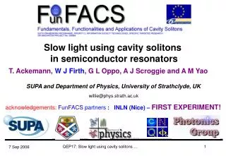
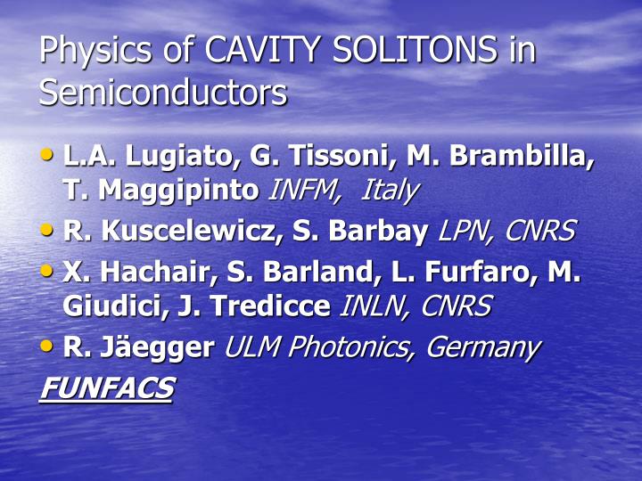
Physics of CAVITY SOLITONS in Semiconductors. L.A. Lugiato, G. Tissoni, M. Brambilla, T. Maggipinto INFM, Italy R. Kuscelewicz, S. Barbay LPN, CNRS X. Hachair, S. Barland, L. Furfaro, M. Giudici, J. Tredicce INLN, CNRS R. Jäegger ULM Photonics, Germany FUNFACS. Spatially Extended System.

E N D
Physics of CAVITY SOLITONS in Semiconductors • L.A. Lugiato, G. Tissoni, M. Brambilla, T. Maggipinto INFM, Italy • R. Kuscelewicz, S. Barbay LPN, CNRS • X. Hachair, S. Barland, L. Furfaro, M. Giudici, J. Tredicce INLN, CNRS • R. Jäegger ULM Photonics, Germany FUNFACS
Spatially Extended System • Property: Correlation length much smaller than the size of the system
Some Nonlinear Effects • Strong non linearity • Strong competing mechanisms: Dispersion-non linearity Diffraction-non linearity Possible results: a. pattern formation b. bistability between patterns c. Localized structures, (Rosanov, Opt. Spectrosc.65, 449-450 (1988))
Optical Cavity Soliton: How to generate them? (in theory) Opticalresonator Holding beam Output Nonlinear medium Writing pulses Cavity Solitons Mirror Mirror
Patterns versus Cavity Solitons • Optical patterns may display an array of light spots, but the intensity peaks are strongly correlated with one another, so that they cannot be manipulated as independent objects.
Theoretical Model Brambilla, M., et al. Phys. Rev. Lett.79, 2042-2045 (1997). Spinelli, L. et al. Phys. Rev. A58, 2542-2559 (1998).
Patterns in VCSEL with Injection Ackemann, T., et al. Opt. Lett.25, 814-816 (2000).
CS can also appear spontaneously ........... Numerics Experiment In this animation we reduce the injection level of the holding beam starting from values where patterns are stable and ending to homogeneous solutions which is the only stable solution for low holding beam levels. During this excursion we cross the region where CSs exist. It is interesting to see how pattern evolves into CS decreasing the parameters. Qualitatively this animation confirms the interpretation of CS as “elements or remains of bifurcating patterns”.
The holding beam HB has been tilted in order to vectorially compensate the force exerted on CS by the cavity length gradient across the cavity.
Properties of Cavity Solitons and Localized Structures. 1.- Spatially localized (of course). 2.- Single addressable objects. A single peak structure can be switch on and off independently of the others if the parameter values are « well » choosen. 3.- Intensity or phase gradients can control their position and/or speed of motion.
They move .............. In order to control CSs positions we inject an holding beam in form of interference fringes. The fringe pattern is moved in front of the VCSEL allowing for repositioning of CSs. As the pattern is moved the spatial frequency of the fringes is gradually decreased • As the fringes are moved CSs follow the peak of HB intensity for a wide distance. • CSs “feel” the fringes as their width are comparable to the CSs width • They disappear for exiting from the spatial region where they are stable or for collision against pattern or against other CSs. • Impurities make the path rather random X. Hachair, et al. PRA (2004)
Analysis of the switching process/2 CS build-up time and delay time Experiment Theory The switch-on time of CS after application of the WB is composed by the CS buildup time and a delay time between the WB application and the start of the CS rising front. CS buildup time results around 600 ps, both in experiment and theory. Delay time is a function of parameters, such as WB phase (relative to the HB), WB power and current injection level.
Analysis of the switching process/3 Delay time vs phase Experiment Theory WB phase (relative to the the holding beam) is a critical parameter: delay time is minimum when = 0 both in experiment and theory (Optimal phase is 0) X. Hachair at al. Submitted (2005)
Analysis of the switching process/4 Delay time vs WB power Theory Experiment Delay time decreases when WB power is increased, both in experiment and theory
Analysis of the switching process/5 Delay time vs pumping current Theory Experiment In the experiment, delay time decreases when bias is increased Experiment and theory disagree....
Homogeneous steady state curve (black stable, red unstable) and CS branch as a function of the injected current. I = 1 is transparency, I = 2.11 is the lasing threshold. CS branch extends from I = 1.97 to I = 2.01. The injected field is EI = 0.75 obtained at I = 2.
Numerical results obtained by including temperature variations induced by the excitation current: the switch on time decreases as we increase the current
Quantitative Changes in the switch on time due to noise effects.
Correlation measurements Without holding beam With holding beam
Fronts between a pattern and a homogeneous solution If the fronts are stable, it is possible to create a localized state. The number of high intensity peaks inside the localized structure depends on the distance D between the fronts.
Stability of a front Y. Pommeau, INTERACTION BETWEEN FRONTS Coullet, P., Riera, C., Tresser, C. Stable Static Localized Structures in One Dimension. Phys. Rev. Lett.84, 3069-3072 (2000).
Conclusions • We have proven experimentally and theoretically that Cavity • Solitons in VCSELS below and above laser threshold are robust structures that can be switched on and off by all optical control, and move under the influence of intensity gradients. • The CS switching process has been analyzed in details: • CS build-up time is on the order of half nanosecond, • while the delay time after WB excitation depends • critically on parameters, such as the relative phase between HB and WB, thecurrent injection level, the WB energy • We are able to generate single and multiple peak localized structures structures and to control their generation
I hope you enjoyed the presentation • If not, please ….do not kill me!! • If Yes, Thank you
CAVITY SOLITON is a LOCALIZED STRUCTURE A pattern that can « live » independently in an spatially extended system
CS in Semiconductors: possible applications • Reconfigurable buffer memory • Serial-parallel converter • Shift register • All-optical processor
Numerical simulation showing the intracavity field amplitude. The initial condition are filaments obtained at EI = 0.9, the evolution (1 ns) is with EI = 0.75.
WB peak intensity vs time p 0 0 700 ps 100 ns t Analysis of the switching process/1 To analyse the switching process in details, an EOM (Electro-Optical Modulator) has been used to replace the AOM (Acusto Optical Modulator). WB is a Gaussian pulse injected into the cavity for 100 ns. Time to reach the stationary value is 700 ps WB width: 10 - 20 m WB power: 10 -160 W (HB power: 8.5 mW)
1. Ackemann, T. et al. J. Opt. B: Quantum Semiclass. Opt.2, 406-412 (2000).
Including q(x)=q0-a x Ei = 1.8 Ei= 2.0 q0 = -1 a = 5
Introduce the current crowding effect: I = I(r)= Io-Xexp[-r2/r02] where r=x2+y2. Io: ~20% abovethreshold • Intensity distribution when pumping above threshold
LOCALIZED STRUCTURES Coullet, P., Riera, C., Tresser, C. Stable Static Localized Structures in One Dimension. Phys. Rev. Lett.84, 3069-3072 (2000). SPATIAL STRUCTURES (CONCENTRATED IN RELATIVELY SMALL REGION OF AN EXTENDED SYSTEM) CREATED BY STABLE FRONTS CONNECTING TWO SPATIAL STRUCTURES