Download
1 / 14
170 likes | 314 Views
DON’T CARE CONDITIONS. Functions that have unspecified output for some input combinations are called incompletely specified functions. Unspecified minterms of a functions are called ‘don’t care’ conditions. We simply don’t care whether the value of 0 or 1 is

E N D
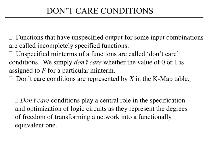
DON’T CARE CONDITIONS • Functions that have unspecified output for some input combinations are called incompletely specified functions. • Unspecified minterms of a functions are called ‘don’t care’ conditions. We simply don’t care whether the value of 0 or 1 is assigned to F for a particular minterm. • Don’t care conditions are represented by X in the K-Map table. • Don’t care conditions play a central role in the specification and optimization of logic circuits as they represent the degrees of freedom of transforming a network into a functionally equivalent one.
DON’T CARE CONDITIONS Example: Simplify the Boolean function
Implementing Logic Circuits with NAND Example: INVERT-OR NAND NAND-OR gates 2-level NAND gates
Verilog Hardware Descriptive Language • Verilog is language that describes the hardware of digital systems • in textual form. • It can be used to represent logic diagrams, Boolean expressions, • and other more complex digital circuits. • There are two applications of HDL processing: simulation and • synthesis. • Logic simulation: representation of the structure and behavior • of a digital system. A simulator interprets the HDL code and produces • an output that predicts the behavior of the hardware before it’s actually • fabricated. • Logic synthesis: process of deriving a list of components and their • interconnections from the system model described in HDL. This • process produces a database with instructions on how to fabricate • a piece of hardware.
SynaptiCAD C:\SynaptiCad\Examples_Book\Book_Tutorials Or you can go directly to the VeriLogger Tutorial: Basic Verilog Simulation
//HDL Example 3-1 //Description of the simple circuit of Fig. 3-37 module smpl_circuit(A,B,C,x,y); input A,B,C; output x,y; wire e; and g1(e,A,B); not g2(y, C); or g3(x,e,y); endmodule port list
Circuit with delay in HDL //HDL Example 3-2 //--------------------------------- //Description of circuit with delay module circuit_with_delay (A,B,C,x,y); input A,B,C; output x,y; wire e; and #(30) g1(e,A,B); or #(20) g3(x,e,y); not #(10) g2(y,C); endmodule
Stimulus to a design: test bench //HDL Example 3-3 //---------------------- //Stimulus for simple circuit module stimcrct; reg A,B,C; wire x,y; circuit_with_delay cwd(A,B,C,x,y); initial begin A = 1'b0; B = 1'b0; C = 1'b0; #100 A = 1'b1; B = 1'b1; C = 1'b1; #100 $finish; end endmodule
Boolean Algebra in HDL //HDL Example //------------------------------ //Circuit specified with Boolean equations module circuit_bln (x,y,A,B,C,D); input A,B,C,D; output x,y; assign x = A | (B & C) | (~B & D); assign y = (~B & C) | (B & ~C & ~D); endmodule