Download
1 / 17
170 likes | 178 Views
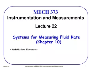
MECH 373 Instrumentation and Measurements. Lecture 21. Measuring Pressure and Temperature (Chapter 9). • Measuring Pressure • Measuring Temperature. Measurement Systems. Measuring Pressure ( Review ).

E N D
MECH 373Instrumentation and Measurements Lecture 21 Measuring Pressure and Temperature (Chapter 9) • Measuring Pressure • Measuring Temperature
Measuring Pressure (Review) Strain gage types Capacitive very low pressures Piezoelectric high-frequency pressure LVDT
Measuring Temperature • Two traditional electronic output devices used for measuring temperature are thermocouples and resistance temperature detectors (RTDs). • Two traditional mechanical measurement devices are called infrared thermometers (for lower temperature)and pyrometers (for higher temperature). Thermocouples • If any two metals are connected together, as shown below, a voltage is developed that is a function of the temperature of the junction. This junction of two metals used as a temperature sensor is called a thermocouple.
Thermocouples operate under the principle that a circuit made by connecting two dissimilar metals produces a measurable voltage (emf-electromotive force) when a temperature gradient is imposed between one end and the other. They are inexpensive, small, rugged and accurate when used with an understanding of their peculiarities. What are thermocouples?
In 1821, T. J. Seebeck observed the existence of an electromotive force (EMF) at the junction formed between two dissimilar metals (Seebeck effect). The voltage is generated by a thermoelectric phenomenon called the Seebeck effect.Seebeck effect is actually the combined result of two other phenomena, Thomson and Peltier effects. Thomson observed the existence of an EMF due to the contact of two dissimilar metals at the junction temperature. Peltier discovered that temperature gradients along conductors in a circuit generate an EMF. The Thomson effect is normally much smaller than the Peltier effect. Thermocouples Principle of Operation
Measuring Temperature • It was later found that the Seebeck voltage is the sum of two voltage effects: the Peltier effect, generated at the junction, and the Thompson effect, which results from the temperature gradient in the wires. • The general simplicity of thermocouples has led to their wide use as temperature measuring sensors. However, there are a number of complications in their use: • The voltage measurement must be made with no current flow. This is because current flow will not only result in resistive losses but will also affect the thermoelectric voltages. Meeting this requirement is not a problem today since electronic voltmeters and date-acquisition systems with very high input impedance are readily available. • Connections to voltage-measuring devices result in additional junctions. As shown in the diagram, there are actually three junctions - the sensing junction and the two junctions where the thermocouple connect to the digital voltmeter (DVM). The voltage reading is thus a function of three temperatures, two of which are of no interest.
Measuring Temperature • The solution to this problem is shown below. Two thermocouples are used, the second being a reference junction. The reference junction is held at a fixed, known temperature, most commonly the temperature of a mixture of pure water and pure ice at 1 atm (0°C). • There are still two junctions at the DVM terminals, but each of these junctions consists of the same two materials, and if the two terminals can be held at the same temperature, the terminal voltages will cancel out. • The two terminals can be held at the same temperature by placing them both in the same thermally insulated box or by mechanically connecting them with thermally conducting but electrically insulating structures.
Measuring Temperature • With the known reference junction temperature, the measured voltage is a unique function of the materials of the thermocouple wires and the temperature of the sensing junction. • Finally, the voltage depends on the composition of metals used in the wires to form the thermocouple. This problem is solved by restricting the materials used to construct thermocouples. When wires and wire pairs are manufactured, standard calibration curves can be used to determine the temperature based on measured voltage. • The following table lists common thermocouple pairs.
Measuring Temperature • The following table lists voltages as a function of temperature for common thermocouple pairs.
Measuring Temperature • • Accuracy of thermocouples depends on the type of the thermocouple, the quality grade of the thermocouple (manufacturers supply different quality grades), and the temperature range. • • There are many factors that must be considered in selecting thermocouples for a given application. It includes • - Sensitivity (voltage per degree temperature change) • - Linearity of output • - Stability and corrosion resistance • - Temperature range • - Cost • • Type R and type S thermocouples are very expensive and not very sensitive; however, they are satisfactory at high temperatures (up to 1768°C) and are resistant to a number of corrosive chemicals. • • Type C thermocouples are usable to very oxidizing environment. • • Type T thermocouples are inexpensive and very sensitive but corrode rapidly at temperatures over 400°C.
Thermocouple Material Vs EMF Types T, J, and K are most commonly used thermocouples
Measuring Temperature • • Type K thermocouples are popular for general use since they are moderately priced, reasonably corrosion resistant, and usable at temperatures up to 1372°C. They also have relatively linear output, which means that for applications in which accuracy requirements are not to severe, the temperature can be computed by assuming a linear relationship between temperature and voltage. • • Thermocouples can be purchased in a number of forms: • - Purchase wires and form a thermocouple junction by welding or soldering the ends of the wire. • - Purchase the wires with the junction already formed by the manufacturer. • • Manufacturers also supply lead wire to connect the sensing probe to the voltage-measuring device. It usually consists of two conductors contained in a plastic sheath. • • In some cases several thermocouples are connected in series in a device called a thermopile, as shown in next slide.
Measuring Temperature • When arranged in this manner, the voltage output to the display is n times the voltage of a single junction, where n is the number of thermocouples in the series. This increases the sensitivity of the system. It also provides a method to average several thermocouples, which are distributed in a spatial region. • Thermopiles are also used in some applications as a power source.
Measuring Temperature • For data-acquisition systems, the following arrangement is used • Each of the thermocouples is connected to a channel of the data-acquisition system (DAS) in an insulated, constant-temperature connection box. The thermocouples then effectively measure the temperature difference between the measurands and the box. One channel is reserved for the reference junction. Software (e.g. LabView) is then used to evaluate the correct voltage by subtracting the reference voltage from the voltage read from the individual channels.
Measuring Temperature Example: Consider standard chromel-alumel thermocouple circuit shown below. (a) Find the voltage measured by the DVM; (b) If the DVM measures 17.51 mV, what would be the temperature T1?
Measuring Temperature Example: Consider standard chromel-alumel thermocouple circuit shown below. (a) Find the voltage measured by the DVM; (b) If the DVM measures 17.51 mV, what would be the temperature T1? Solution: Use Table 9.2 for K-type thermo-couple. T1= 492