Download
1 / 43
440 likes | 454 Views
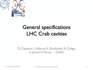
Many thanks to R. Calaga and T. Mastoridis for help, material and comments. LLLRF considerations for the LHC Crab CAVITies. P. Baudrenghien CERN BE-RF HiLumi LHC 2013, Daresbury , Nov 13,2013. Content. Proposed layout in the LHC tunnel LLRF challenges Operational scenario

E N D
Manythanks to R. Calaga and T. Mastoridis for help, material and comments LLLRF considerations for the LHC CrabCAVITies P. BaudrenghienCERN BE-RF HiLumi LHC 2013, Daresbury , Nov 13,2013
3rd HiLumi LHC-LARP Content • Proposed layout in the LHC tunnel • LLRF challenges • Operational scenario • LLRF hardware • Planning • Conclusions
3rd HiLumi LHC-LARP Proposed layout
3rd HiLumi LHC-LARP LHC layout Main (ACS) RF system Crab Cavity RF Crab Cavity RF
3rd HiLumi LHC-LARP TX and LLRF in new service galleries • We have ~300 m distance between crabbing and un-crabbing cavities • We propose to dig-out a short gallery running parallel to the tunnel on both sides of IP1 and IP5 for the RF power (TX) and LLRF electronics • Such a gallery exists in IP4 (ex LEP klystron gallery)
3rd HiLumi LHC-LARP LLRF challenges
3rd HiLumi LHC-LARP Challenges • Fine-phasing of the CC kick with the individual bunch centre • Reduce the cavity impedance at the fundamental to prevent transverse Coupled-Bunch instabilities • Prevent transverse emittance blow-up caused by RF noise • Manage beam loss following a klystron trip or cavity quench
3rd HiLumi LHC-LARP The Crab Cavity systems (IP1 and IP5)
3rd HiLumi LHC-LARP Fine Phasing
3rd HiLumi LHC-LARP Phasing the CC with the bunch centre • A phase error (w.r.t. bunch centre) causes an offset of the bunch rotation axis. This results in a transverse offset Dxat the IP • 1 deg RF phase (7 ps) leads to Dx = 1mm (1/5h transverse beam size) • The stringent requirement concerns transverse emittance growth caused by RF phase noise at frequencies intersecting one of the betatron bands. Much larger offset can be accepted if static or at frequencies significantly below 3 kHz (first betatron band).
3rd HiLumi LHC-LARP A detour: Phase modulation in the Main cavities
3rd HiLumi LHC-LARP Present scheme • RF/LLRF is currently setup for extremely stable RF voltage (minimize transient beam loading effects). Less than 1 RF phase modulation over the turn with 0.35 A DC (7 ps) • To continue this way, we would need at least 300 kW of klystron forward power at ultimate intensity (1.7E11 ppb) • Klystrons saturate at 200 kW with present DC parameters (ultimately 300 kW). • Sufficient margin necessary for reliable operation, additional RF manipulations etc. • At 7 TeV, 1.1 A DC, the synchrotron radiation loss is 14 keVper turn, or 27 pW • All RF power is dissipated in the circulator loads • The present scheme cannot be extended much beyond nominal. Required klystron power for 1.15e11 ppb, 25 ns, 7 TeV, 1.7e11 ppb, 25 ns, 450 GeV, 1.7e11 ppb, 25 ns, 7 TeV P. Baudrenghien, T. Mastoridis, “Proposal for an RF Roadmap Towards Ultimate Intensity in the LHC", IPAC 2012
3rd HiLumi LHC-LARP Proposed RF phase modulation scheme • In physics • We will accept the modulation of the cavity phase by the beam current (transient beam loading) and adapt the voltage set point for each bunch accordingly • The klystron drive is kept constant over one turn (amplitude and phase) • The cavity is detuned so that the klystron current is aligned with the average cavity voltage • Needed klystron power becomes independent of the beam current. For QL=60k, we need 105 kW only for 12 MV total • Stability is not modified: we keep the strong RFfdbk and OTFB • The resulting displacement of the luminous region is acceptable • During filling • It is desirable to keep the cavity phase constant for clean capture. Thanks to the reduced total voltage (6 MV) the present scheme can be kept with ultimate. Modulation of the cavity phase by the transient beam loading in physics. 2835 bunches, 1.7 1011 p/bunch, 1.5 MV/cavity, QL=60k, full detuning (-7.8 kHz).
3rd HiLumi LHC-LARP Consequences for the CC • If the CC follows the phase modulation • Forcing the CC to follow the fast phase modulation (-10 degrees @ 400 MHz in the 3.2 ms long abort gap) results in huge power requirement • With the HiLumiparameters (2808 bunches, 2.2E11 p/bunch, 1.11 A DC, 3.2 ms long abort gap ), assuming 3 MV per crab cavity, 300 WR/Q, we need an absolute minimum of 170 kW per cavity. This minimum is achieved with a QL=44000 • With QL=500000, we need 950 kW
3rd HiLumi LHC-LARP Consequences for the CC (cont’d) • Fixed CC phase • Keeping the Crab Cavity phase constant over the turn will result in a phase error df, with respect to the individual bunch center • This phase error causes an offset of the bunch rotation axis, resulting in a transverse displacement Dxat the IP • For aphase drift of 30 ps, the transverse displacement is 5 mm, approximately equal to the transverse beam size • Fortunately the filling patterns are identical for both rings (except for the first six or twelve bunches batch) and the phase errors will be equal for colliding pairs in IP1 (ATLAS) and IP5 (CMS) because the bucket numbering convention makes the bucket one of both rings (first bucket after the abort gap) “collide” in IP1 and IP5 • There will therefore be no loss of luminosity, only a modulation of the transverse position of the vertex over one turn. This is acceptable by the experiments
3rd HiLumi LHC-LARP Impedance
3rd HiLumi LHC-LARP Machine Impedance • The HighLumi LHC will accelerate 1.1 A DC current per beam (compared to 0.35 A DC in 2012) • The Crab Cavities will introduce a series of Narrow-Band resonators in the machine (fundamental plus HOMs) • Control of the fundamental is the responsibility of the LLRF. • At the fundamental one cavity presents a transverse impedance around 2.5 GW/m to be reduced below 1 MW/m (threshold calculated for physics conditions, assuming 6 cavities per beam.plane, and a 60 ms damping time from the active transverse damper)
3rd HiLumi LHC-LARP RF feedback onCrab Cavities • With strong RF feedback, the minimal effective transverse impedance scales with the loop delay T • Assume 300 W R/Q and 1ms loop delay, we get Rmin= 6.3 MW/mper cavity • The impedance is reduced by 400 linear bit still way too much compared to the instability threshold • Fortunately, for a resonator whose BW covers several revolution frequency lines, what counts is not just the impedance but the growth rate
Without RF feedback, the cavity impedance at 400 MHz is much narrower than the revolution frequency (for QL=106) and the 1 MW/m threshold must be respected With the RF feedback active, the effective impedance covers several revolution frequency lines and stability is defined by the competition between damping and undamping mode The instability growth rate for mode l is the difference between real impedance on the two ±(l wrev+wb) sidebands of the wRF The growth rate is much reduced if the effective impedance is symmetric around wRF 3rd HiLumi LHC-LARP Instability growth rate • Real part of the cavity impedance with RF feedback. • In physics the cavity will be on-tune and its impedance does not affect stability • During filling and ramping the cavity will be detuned by an amount (-1.5 kHz?) much smaller than the few 100 kHz BW of the effective impedance Very important reduction to the growth rate, from the symmetry
3rd HiLumi LHC-LARP Transverse: Betatron Comb filter We can further reduce the growth rate by selectively correcting the effective impedance on the betatron lines • One-turn delay filter with gain on the betatron bands • To keep 10 dB gain margin, the gain on the betatron lines is limited to ~ 6 linear (16 dB) • 2 N Poles on the betatron frequencies • Reduction of noise PSD where the beam responds • Reduction of the effective cavity impedance thereby improving transverse stability • Zeros on the revolution frequency lines • No power wasted in transient beam loading compensation with off centered beam • Betatron comb filter response with a=31/32 and non-integer Q=0.3. Observe the high gain and zero phase shift at (n ±0.3) frev
3rd HiLumi LHC-LARP RF Noise
3rd HiLumi LHC-LARP Cavity RF Noise • RF feedback noise sources: • The RF reference noise nref • The demodulator noise (measurement noise) nmeas • The TX (driver) noisendr(process noise). It includes also the LLRF noise not related to the demodulator • The Beam Loading IbDx • We get Main coupler • Beam Loading response = effective cavity impedance Zeff(s) • Equal to ~1/KG in the CL BW • Increase of K decreases Zeff within the CL BW • Within the CL BW, TX noise and beam loading are reduced by the Open Loop gain KG • Closed Loop response CL(s) • Equal to ~1 in the CL BW • Increase of K increases the BW • Within the BW, reference noise and measurement noise are reproduced in the cavity field
3rd HiLumi LHC-LARP Scaling the ACS noise to CCs Noise in the 10Hz-1kHz range is not an issue as the first betatron band is around 3 kHz TX noise is important in the band extending to 20 kHz. It is reduced by loop gain and scales as 1/Sqrt[QL]. Tetrodes are less noisy than klystrons In the 10kHz-400 kHz range the noise level is defined by the demodulation of the antenna signal. The noise BW increases with the loop gain • ACS SSB phase noise Power Spectral Density in dBc/Hz. First betatron band In the transverse plane the first betatron band is at 3 kHz. Reference noise is not an issue. The performances will be defined by TX noise and measurement noise
3rd HiLumi LHC-LARP Scaling the ACS to crab • The beam will sample the noise spectrum in all betatron side-bands • Assume a SSB phase noise of L= -135 dBc/Hz or S= 6.3E-14 rad2/Hz, thensumming the noise PSD from DC to + 300 kHz over all betatron bands, we get 300/11 x 2 x 6.3E-14 rad2/Hz =3.4E-12 rad2/Hz from DC to the revolution frequency • A “copy” of the LHC ACS design (300 kW klystron !) would generate 3.7E-8 rad2 white noise, that is 2E-4 rad rms or 1.1E-2 degrms phase noise @ 400 MHz
3rd HiLumi LHC-LARP Resulting transverse emittance growth • Simulations are numerous. In the longitudinal plane I have used • For the CC I use an early analysis indicating that 2 nm rms white noise would lead to 1% emittance growth per hour.(R. Calaga et al., small angle crab compensation for LHC IR upgrade, PAC07). • The 2E-4 rad rmscorrespond to 10 nm rms • Scaling emittance growth with the noise power, leads to a predicted 10% emittance growth per hour, from a “copy” of the LHC ACS design • Improvements are expected because • The damper gain can be increased compared to the PAC07 figures • The CC TX (50 kW tetrode) will be less noisy than the ACS klystron • And an additional reduction (16 dB?) will come from the betatroncomb A simplified analysis is needed to pilot the LLRF developments, such as a very low-noise demodulator. Measurements of TX noise are also urgent.
3rd HiLumi LHC-LARP Trade-off • A weak coupling (large QL) • Reduces the effect of TX and LLRF noise. Good • But we want to keep BW sufficient so that microphonics are located within the cavity BW • A large feedback gain • Reduces the instability growth rates. Good • Limits the effect of TX and LLRF noise. Good • Increases the integrated effect of measurement noise by increasing the BW. Bad • Trade-off required • Will depend on the TX noise
3rd HiLumi LHC-LARP RF Power vs. QL • Candidate TX: 50-100 kW tetrode as used in the SPS 352.2 MHz system in the 1990’s • TX linked to the cavity via a circulator. 3 MV RF. R/Q = 300 W. 1.1 A DC current, 1 ns 4s bunch length (1.8 A RF component of beam current). Cavity on tune. • Yellow trace: beam centered • Blue trace: x=+1 mm offset • Red trace: x=-1 mm offset For 1 mm offset, the range of acceptable QL (P < 30 kW) is • 2.5 105< QL <1.8 106 for R/Q=300 W • 8 104< QL <6 105 for R/Q=900 W Low values preferred for tuning (microphonics).
3rd HiLumi LHC-LARP Keeping crabbing and uncrabbing kicks equal Improves precision and compensates for a single-cavity fault
3rd HiLumi LHC-LARP Coupled feedback • Following a CC quench or a TX trip, the crabbing will not be limited to the IP region but will continue around the ring • The tails of the bunch transverse distribution will be collimated out, resulting in huge losses and the beam dump will be triggered. It takes up to 3 turns to react • The LLRF can help minimizing the losses during that transient. The idea is to implement a coupled feedback, acting on all CC cavities, and keeping crabbing and un-crabbing equal • In the case of a crabbing cavity trip, it would ramp the un-crabbing voltage down, tracking the total crabbing voltage
3rd HiLumi LHC-LARP The Crab Cavity systems (IP1 and IP5) • Voltage change following a klystron trip is defined by QL. • Voltage variations following a quench is not well known. To be studied/experimented (SPS test-bench)
3rd HiLumi LHC-LARP Operational scenario
3rd HiLumi LHC-LARP Operational scenario • Strong RF feedback and tune controls are ON at all time • During filling, ramping or operation with transparentcrab cavities, we detune the cavity (1.5 kHz?) but keep a small field requested for the active Tuning system. As the crabbing kick is provided by three cavities we can use counter-phasing to make the total field invisible to the beam. The RF feedback is used with the cavity detuned to provide stability and keep the Beam Induced Voltage zero if the beam is off-centered. We can use the demanded TX power as a measurement of beam loading to guide the beam centering. • ON flat top • Reduce the detuning while keeping counter-phasing so that the total voltage is zero. The RF feedback keeps the cavity impedance small (beam stability) and compensates for the beam loading as each cavity moves to resonance • Once the cavity detuning has been reduced to zero, we drive counter-phasing to zero.Any luminosity leveling scheme is possible by synchronously changing the voltage or phase in each crab cavity as desired.
3rd HiLumi LHC-LARP LLRF HARDWARE
3rd HiLumi LHC-LARP LLRF Hardware • Very close synergy with the 800 MHz Harmonic cavities in the SPS and the Linac4 352.2 MHz system • On-going commissioning of the Linac4 prototype with the RFQ • Commissioning of the 800 MHz version at SPS restart (2nd half 2014) • Hardware must be tuned for 400 MHz and firmware must be developed to have prototypes ready for the SM18 test by 2015, in advance for the planned 2016 installation
3rd HiLumi LHC-LARP Interconnection with the paired cavity(ies) Coupled feedback Gain increased on the betatron bands Measurement of bunch phase modulation Field control fully integrated with the rest of the LHC by using standard FGCs • For each Crab Cavity we have a Cavity Controller including: • An RF Feedback Loop for noise and beam loading control • A TX Polar Loop to reduce the TX noise and stabilize its gain/phase shift • A Tuner Loop to shift the cavity to a detuned position during filling and ramping. Then smoothly bring the cavity on-tune with beam for physics • A field Set Point for precise control of the cavity field.
3rd HiLumi LHC-LARP SPS 800 MHz TWC prototype G. Hagmann BE-RF-FB designer SRAM 2x8 Mbyte for diagnostics 2 x Duplex Optical Serial Links 2 in & 2 out 2Gbits/s (≤3.2Gbits/s) Xilinx Virtex 5 SX VME P1 backplane for slow controls/readout SSB Modulator IF (I & Q) ≈25MHz Dual TxDac 16 bits • Dedicated backplane (P2): • Power Supply • Clocks • Interlocks • … 4x RF Demodulator RF&LO mixing IF ≈25MHz 14 bits ADC Fs=4·IF ≈100MHz LO Distribution
3rd HiLumi LHC-LARP SPS 800 MHz TWC prototype 2 x Duplex Optical Serial links 2 inputs 2 outputs Status LED RF output RF inputs (4x) G. Hagmann BE-RF-FB designer LO input
3rd HiLumi LHC-LARP ACS LLRF. 1 rack/ 2 VME crates, per cavity in a Faraday Cage in the UX45 cavern
3rd HiLumi LHC-LARP PLANNING
3rd HiLumi LHC-LARP Planning • 2013-2014 Cavity Testing • 2015-2016 LLRF developments • 2016-? SPS tests: 2 cavities in one cryostat • 2015-2017 (LS2?) Prototype Cryomodule • 2018-2020 (LS3?) Production • In operation in the LHC after LS3 • Proposed SPS cryomodule with 2 Crab Cavities. The cryomodule is designed to accept all three CC makes Courtesy EN-MME • SPS testbench with 2 Crab cavities in the LSS4. The cryomodule can be moved in and out of the beam line (2016-)
3rd HiLumi LHC-LARP conclusions
3rd HiLumi LHC-LARP Conclusions • All requirements appear very demanding but not unrealistic • We have possible LLRF solutions to be tested in the SPS test-bench. This will give indications on the phase error, impedance and RF noise • We will also observe the behavior of the RF field following a quench and validate the coupled-cavity feedback idea • Crab Cavity must be made compatible with the phase modulation in the main cavities planned for the HiLumi era • This is all very challenging but…
Thank you for your attention 3rd HiLumi LHC-LARP Crabs can adapT