Download
1 / 17
190 likes | 597 Views
4-bit Decimation Filter. Rashmi Joshi Siu Kuen(Steve) Leung Cuong Trinh Advisor: Dr. David Parent December 5, 2005. Agenda. Abstract Introduction Summary of Results Project Details Results Cost Analysis Conclusions. Abstract.

E N D
4-bit Decimation Filter Rashmi Joshi Siu Kuen(Steve) Leung Cuong Trinh Advisor: Dr. David Parent December 5, 2005
Agenda • Abstract • Introduction • Summary of Results • Project Details • Results • Cost Analysis • Conclusions
Abstract • We designed a 4-bit Decimation Filter. The system operates at 142.8 MHz, uses less than 192.5 mW per clock of power, and occupies an area of 550x890 mm2.
Introduction • Decimation filter is used to average the output of an A/D converter. The function of a decimation filter is to remove all of the out-of-band signals and noise, and to reduce the sampling rate by k. • Decimation filter samples input data until k samples have been accumulated. The output is then the sum of k (=4) accumulated samples. The frequency of the output is thus 4 times less than that of the input.
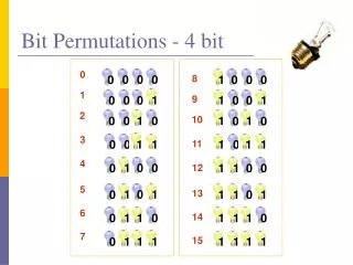
Project Summary The design consists of a nand-based 7-bit ripple carry adder, a divide-by-4 counter, and 3 stacks of D flip-flops. The first stack is at the input side. The second stack serves as an accumulator. A divide-by-4 counter clocks the out put flip-flops and resets the accumulator.
Longest Path Calculations Tphl = 6.666ns/20 = .333ns
Cost Analysis • Estimated time spent on each phase of the project: • verifying logic (1 week) • verifying timing (1 week) • layout (3 weeks) • post extracted timing (2 weeks)
Lessons Learned • LVS failure due to same metal layer wire crossing. This can be spotted in single layer view and LVS high-lighted errors in analog-extracted view. • Spend more time on researching on alternative design options.
Summary • This project is a good start for students to learn IC design flow with CAD tool. • The design can run at 142.8 MHz, has an area of 550x890 mm2, and uses less than 192.5 mW per clock of power. • The design can run faster than 150 MHz if a CLA adder is used instead of RC adder.
Acknowledgements • Thanks to our family for support • Thanks to Cadence Design Systems for the VLSI lab • Thanks to Professor David Parent for guidance