Download
1 / 37
370 likes | 495 Views
NCSX General Requirements Document (GRD). Hutch Neilson NCSX GRD Peer Review April 3, 2003 Agenda Introduction and Objectives- H. Neilson Structure of the GRD; NCSX Specification Hierarchy- W. Reiersen Requirements and Issues- H. Neilson. Introduction and Objectives. Team

E N D
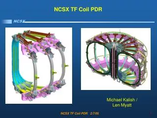
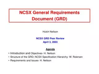
NCSX General Requirements Document (GRD) Hutch Neilson NCSX GRD Peer Review April 3, 2003 Agenda Introduction and Objectives- H. Neilson Structure of the GRD; NCSX Specification Hierarchy- W. Reiersen Requirements and Issues- H. Neilson
Introduction and Objectives Team • John Schmidt, Chair • Wayne Reiersen, Cog • Hutch Neilson, RLM • Charles Neumeyer • Mike Zarnstorff Objective: A GRD that is adequate for the project’s next steps. • Establishing the technical baseline. Will be part of the performance baseline (along with cost and schedule). • Establishing a sound basis for lower-level “design-to” specifications, especially for the modular coils and vacuum vessel.
Recent History and Plan May, 2002 Draft F presented at CDR. August, 2002 Draft F circulated for project review. Many comments received. Comments logged in GRD tracking log. March 28, 2003 Pre-peer review Draft (G) issued with tracking log documenting proposed disposition of comments. April 3, 2003 Peer Review Updated Draft (H) and tracking log issued, incorporating comments received by April 1. April 18, 2003 Next Draft (I), incorporating peer review findings, to be circulated for signature. In parallel, to be distributed to NCSX PAC and PDR members for comment. June 10, 2003 Issue to PDR Reviewers.
Scope of Project and GRD The GRD is the top-level spec for the NCSX Major Item of Equipment (MIE) Fabrication Project, which includes: • All equipment required at First Plasma. • Refurbishment and installation of 3 MW of neutral beam heating power. • Capability to accommodate certain specified equipment as future upgrades. • Achievement of the First Plasma milestone defined in the Project Execution Plan. • First Plasma characteristics. • First Plasma equipment performance levels. GRD performance requirements flow down to lower-level subsystem development (or “design-to”) specs according to an allocation matrix (Section 3.7) TBD’s and TBR’s can exist and still meet present objectives. • To be determined (TBD): usual meaning. • To be revised (TBR): requirement subject to revision after cost-benefit implications are more fully understood.
Initial Facility Startup Before First Plasma: • Capability to verify that requirement are met, via a combination of examination, test, demonstration, and analysis. (Section 4) • Plans to be documented in NCSX Test and Evaluation Plan. • Capability to perform an Integrated System Test Program (ISTP) to verify that system operates safely and as expected.
Pre-Run Facility Startup / Post-Run Shutdown(After / Before a Major Outage) • Pre-run: capability to perform a controlled startup and verify that systems are functioning correctly. • Subset of full ISTP • Post-run: capability to perform a controlled shutdown Coil Cooldown / Warmup • Cooldown: RT to 80K within 96 hours (TBR). • Warmup: 80K to RT within 96 hours (TBR). • 150 cooldown/warmup cycles.
Vacuum and Pumping Base Vacuum • Base pressure ≤210-8 torr at RT (≤210-7 torr at First Plasma). • Global leak rate ≤110-5 torr-l/s at RT (≤110-4 torr-l/s at First Plasma). • Measurements: standard ion gauges, RGA. Fast neutral pressure gauge as upgrade. • Attachments have their own pumping/conditioning systems if not permanently open to the vacuum vessel. • In-vacuum or vacuum-interfacing systems to be designed for high-vacuum compatibility (no trapped volumes or virtual leaks) • System to allow leak checking and leak repair of vacuum vessel. Torus pumping • Pumping speed ≥2,600 l/s at the torus using the PBX-M TMPs (or equivalent). Post-Run Venting • Capability to vent the vacuum vessel in preparation for an opening.
Bakeout During Bakeout • Vacuum vessel shell and ports maintained at 150±25 C. • Future carbon PFCs to be maintained at 350±25 C. (upgrade) • Cryo-cooled coils capable of being kept at ≤90 K. (TBR) • Capable of GDC. • Any of: hydrogen, deuterium helium, methane. • Windows shuttered to prevent coating. • Insulators shielded to prevent coating and high-resistance shorts. • Neutral beams isolated. Bakeout timeline • Vessel and internal components raised to temperature within 36 hrs. (TBR). • Can be maintained at temperature indefinitely. • Vessel and internal components returned to 40 C within 36 hrs. (TBR).
Plasma Chamber Conditioning(Start of an Operating Day) Boronization • Capability for boronization of all surfaces with line-of-sight to the plasma (upgrade). Lithiumization • Capability to apply Li coatings, by either Li pellets or Li spray or other techniques (upgrade).
Pre-Pulse Initialization and Verification Pre-Pulse Temperatures • Interior vacuum vessel surfaces and in-vessel components except PFCs return to prescribed temperature in the range of 40 C (TBR). • PFCs have a minimum pre-pulse temperature of 40 C (TBR). • Interior vacuum vessel surfaces and in-vessel components except PFCs capable of being maintained at 40 C (TBR) in the presence of a 210 C liner. (upgrade requirement for compatibility with Lithium liner) Glow Discharge Cleaning • Capability for GDC between pulses with VV and all in-vessel components at pre-pulse temperatures. • Any of: hydrogen, deuterium helium, methane. • Windows shuttered to prevent coating. • Insulators shielded to prevent coating and high-resistance shorts. • Neutral beams isolated.
Pulsed Operation Repetition Rate • 15 min. intervals when constrained by coil or PFC cool-down. • 5 min. otherwise. Design Life • >10 years operation in the reference scenarios. • Fatigue life (pulses) operating in the reference scenarios: • 100 per day. • 13,000 per year. • 130,000 lifetime.
Polarities Magnetic Polarity • Facility shall be configured for a standard polarity to have the toroidal field in the negative -direction (clockwise viewed from above). • Determines all other field and coil polarities through stellarator magnetic configuration. • Polarity is capable of being reversed from the standard direction.
Reference Scenarios - 1 Reference Scenario Requirements • 7 Reference Scenarios are specified. • TF, PF, and modular coils shall be designed for all the reference scenarios. • Power systems shall be designed and initially configured for the Initial Ohmic Scenario, and capable of being upgraded to meet all reference scenarios. • At First Plasma, system shall produce First Plasma Scenario with coils cooled to cryo. temperature and energized with their own power supplies. • At First Plasma, coils and power supply performance shall be demonstrated to the following currents • Modular coils: 5 kA TF coils: 3 kA • PF 1 & 2 (CS): 6 kA PF 3-4: 4 kA • PF 5-6: 2 kA Ext. trim coils: 1 kA (temporary supplies.)
Reference Scenarios - 2 Reference Scenario Specifications • First Plasma Scenario • B0≥0.5 T, IP≥25 kA, ≥50% of the iota from stellarator fields. • Initial Ohmic Scenario • Pre-initiation config. w/vacuum iota >0.5 in the outer half of plasma and B0=1.5 T, held for 100 ms. • Inductive plasma initiation and rampup to 154 kA at 1.6 MA/s • Constant current for 300 ms. • 1.7 T Ohmic Scenario (upgrade) • Pre-initiation config. w/vacuum iota >0.5 in the outer half of plasma and B0=1.7 T, held for 100 ms. • Inductive plasma initiation and rampup to 175 kA at 3 MA/s • Constant current for 300 ms.
Reference Scenarios - 3 Reference Scenario Specifications, cont’d. • 1.7 T High Beta Scenario (upgrade) • Pre-initiation config. w/vacuum iota >0.5 in the outer half of plasma and B0=1.7 T, held for 100 ms. • Inductive plasma initiation and rampup to 175 kA at 3 MA/s. • Heating at constant current to >4% in 100 ms. • Constant current and beta for 200 ms. • 1.2 T Long-Pulse Scenario (upgrade) • Pre-initiation config. w/vacuum iota >0.5 in the outer half of plasma and B0=1.2 T, held for 100 ms. • Inductive plasma initiation and rampup to 124 kA at 3 MA/s. • Heating at constant current to >4% in 100 ms. • Constant current and beta for 1.1 ms.
Reference Scenarios - 4 Reference Scenario Specifications, cont’d. • 2 T High Beta Scenario (upgrade) • Pre-initiation config. w/vacuum iota >0.5 in the outer half of plasma and B0=2 T, held for 50 ms. • Inductive plasma initiation and rampup to 205 kA at 3 MA/s. • Heating at constant current to >4% in 100 ms. • 350 kA Ohmic Scenario (upgrade) • Pre-initiation config. w/vacuum iota >0.5 in the outer half of plasma and B0=1.8 T, held for 100 ms. • Inductive plasma initiation and rampup to 350 kA at 3 MA/s • Constant current for 300 ms.
Flexibility Requirements at B=1.7 T: Coils shall be designed, power systems shall be upgradeable, to be able to vary: • QA: vary effective ripple from 1 to 10 times nominal. • External iota: from -0.2 to +0.2 (TBR) about the reference, @constant shear. • Shear: vary global shear ((a)–(0)) from -0.2 to +0.2 (TBR) about the reference, @constant (0). • Beta limit: reduce kink stability beta limit to 1%, from reference value of ~4%. • Radial & vertical position: radial by ±16 cm, vertical by ±2 cm, both TBR. • Feedback control as a future upgrade.
Discharge Termination Normal Termination • Capability to perform a controlled shutdown of the plasma and associated subsystems at the conclusion of a pulse. Abnormal Termination • Capability to shut down the plasma and associated subsystems if a condition occurs during experimental operation (i.e. a pulse) that could cause significant equipment damage or injury to personnel.
Field Errors & Eddy Currents Field Errors • Field Error Compensation Coils (a.k.a. External Trim Coils) shall be provided to compensate for fabrication errors. • The toroidal flux in island regions due to fabrication errors, magnetic materials, or eddy currents (with compensation) shall not exceed 10% of the total toroidal flux in the plasma. Eddy Currents • Time constant of longest-lived eddy current eigenmode of the VV and in-vessel structures shall be less than 10 ms. • Stellarator core structure (except coils) shall include electrical breaks to avoid having a toroidally continuous current path. • Time constant of longest-lived eddy current eigenmode of the conducting structure outside the VV (except coils) shall be less than 20 ms. • Eddy currents in conducting structures surrounding the plasma shall not give rise to unacceptable field errors. • Stellarator symmetry shall be preserved in the design of the VV, in-vessel structures, and conducting structures outside the VV in the stell. core.
Disruptions • Facility shall be designed to withstand EM forces due major disruptions. • Characterized by instantaneous decay of the plasma with a max. current of 350 kA. • (Iinstantaneous decay assumed for simplicity. Induced voltage effects are ignorable because of the relatively low current and continuous vacuum vessel.)
Plasma Heating: Neutral Beams • Initial complement: • 3 MW with minimum 0.3 s pulse length from two of the PBX-M beams. • One co- and one counter-. • Aimed such that the tangency radius is inside the magnetic axis and the beam does not intercept the inboard first wall. • At First Plasma: • Beamlines shall be mechanically installed. • All cabling and other connections shall be installed, • Beamline operating vacuum shall be achieved. • Beamline cryopanels shall be cooled down to cryogenic temperature. • Ultimate complement (upgrades): • Up to 6 MW and up to 1.2 s from all four PBX-M beams. • Two possible configurations: 2 co-/2 counter- and 3 co-/1 counter-.
Plasma Heating: RF Upgrades Ion Cyclotron Heating • 6 MW @20-30 MHz with 1.2 s pulse length. • 3 sets of launchers on the inboard side, one at each v=0.5 cross section. Electron Cyclotron Heating • 3 MW @70-140 GHz with 1.2 s pulse length.
Power Handling and PFCs - 1 Initial PFC Configuration • Poloidal limiters on the inboard side at the v=0.5 cross section. Material: carbon. PFC Configuration Upgrades to be Accommodated • Coverage: up to 100%. • Divertor. • Divertor pumping: with a slot that provides passage to an actively pumped (w/ cryopump or Ti getter pump) plenum. • Electrical biasing: bias regions of the plasma boundary relative to each other and to the vacuum vessel. • Armor: to protect the vacuum vessel, port extensions, and in-vessel components from NB shinethrough and fast ions lost from the plasma.
Power Handling and PFCs - 2 Maximum Plasma Heating Power • 350 kW for 0.3 s for the Initial Ohmic Scenario. • Upgrade: handle heat loads associated with up to 12 MW of plasma heating power for 1.2 s (including 6 MW of NBI). Maximum Component Surface Temperature • For carbon-based PFCs: 1200 C.
Plasma Fueling Fuel Species • Hydrogen, deuterium, helium Gas Injection • Programmable system, one injector per period, max. flow rate ≥50 torr-l/s per injector. Capable of H, D, or He. • Accommodate as upgrades: • Feedback control on real-time density measurements. • One inboard injector per period (capable of gas or pellets). • One outboard supersonic injector per period. Pellet Injection • Guide tubes to accommodate inboard pellet injector upgrade. • One injector capable of repetitive H or D pellet injection (upgrade).
Diagnostics General Requirement: provide, or accommodate as upgrades: • Diagnostics critical to research goals. • Diagnostics required for plasma control and operational purposes. Implementation • Provide all diagnostics required for Initial Operation (Phase I) and Field Line Mapping (Phase II), per Table 3-2. • Accommodate as upgrades, all diagnostics required for Initial Ohmic (III), Initial Aux. Heating (IV), Confinement and High Beta (V), and Long Pulse (VI) Phases, per Table 3-2.
Instrumentation & Control / Data Acquisition General Requirement- a system that allows for: • Coordination of of operations. • Acquisition, archiving, and display of all pertinent information Data archiving requirements • Data to be retrievable with widely available cross-platform software. • Data protected from loss or destruction by maintaining multiple copies, including off-site storage. Complete integrated subsystem tests as required for First Plasma • Safety interlock system. • Timing and synchronization system. • Power supply real time control system. • Data acquisition system.
External Interface Requirements / Assumptions Facility- NCSX assumes test cell, basement, and adjacent areas received with adequate: • Protection from outdoor environment. • Lighting. • Temperature, humidity, air exchange control. • Fire suppression. Water systems • NCSX assumes facility water systems received in fully operational condition. • NCSX will provide cooling loops for NCSX subsystems. Electrical Power • Power for TF, PF, and modular coils from D-site expt’al. power system. Utility Gas Systems • NCSX will provide nitrogen and compressed air utility services.
Test Cell Compatibility Maximum Lift • Max. lift shall not require overhead crane capacity exceeding 30 tons. Maximum Dimensions • Components and subassemblies must fit through the door (18 ft. x 16 ft.) Maximum Floor Loading • TBD
Materials Magnetic Materials • Must have µr<1.02 unless otherwise authorized. Vacuum compatibility of vessel and in-vessel metallic components • Electropolish when practicable, otherwise mechanically lapped to 30 µ-in. finish. • Vacuum compatible materials, degreased and cleaned and, when practicable, baked prior to installation. • In-vessel materials to be approved by project for vacuum compatibility. Plasma-facing surface materials • Initial PFCs shall be carbon-based (graphite or CFC). • In-vessel materials shall be compatible with lithium, to facilitate use of a lithium liner as a possible future upgrade.
Design Criteria, Etc. Structural and Cryogenic • NCSX Structural and Cryogenic Criteria Document Seismic • DOE Standards (DOE-STD-1020-2002). Corrosion • Use protective surface treatments or finishes to inhibit corrosion. • Avoid contact between dissimilar metals where possible. Labeling, Workmanship, and Interchangeability • Sections 3.3.3, 3.3.4, 3.3.5
Reliability, Availability, and Maintainability • Availability: design consistent with >75% availability after initial shakedown and commissioning. • In-vessel entry: Design for in-vessel personnel entry and access for installation and maintenance. • Work platform: Provide platform for access to device and diagnostics. • Recovery from failure: Provide for recovery from every credible failure mode. • Machine disassembly / reassembly: within 1 year (TBR) for part replacement or reconfiguration requiring disassembly. • Lift provisions: eyes or sling attachments for assemblies exceeding two-person manual lift limits.
Electromagnetic Requirements Electrical Grounding • Single-point grounding system, per NCSX Grounding Specification for Personnel and Equipment Safety. • Ground-loop detection system to facilitate maintaining ground system integrity. • Voltage isolation of 5 kV (TBR) between the vacuum vessel and systems attached to it. RF Shielding • TBD.
E.S. & H. Requirements Addressed in Section 3.3.6: • General safety. • No uncontrolled safety or health hazards. • Detect abnormal operating conditions and safeguard equipment, personnel. • Radiation monitoring. • Controlled access system. • Toxic gases • Oxygen depletion. • Vacuum implosion. • Personnel safety: applicable OSHA requirements per 29CFR1910. • Hazardous materials exposure limited by OSHA permissible exposure limit. • Flammability. • Fire suppression: meets DOE O 420.1 and PPPL ESHD-5008. • Radioactive and hazardous waste handling. • Electrical safety. • Radiological limits (D operation administratively limited)
Human Factors Engineering Addressed in Section 3.3.7 (many TBDs): • Anthropometry (compatibility of work stations, furniture, traffic flow,equipment accessibility with the user population). • Temperature and humidity. • Ventilation. • Lighting. • Emergency lighting per NFPA 101. • Noise • Vibration • Component arrangement (promote operator efficiency and awareness). • Protective equipment (ensure worker access per PPPL directive ESHD-5008). • Display devices. • System controls. • Warning and annunciator systems. • Communication systems.
Quality Assurance Provisions How will we verify that the requirements are satisfied? Four Inspection Verification Methods • Examination • Test • Demonstration • Analysis. Quality Conformance Matrix (Table 4-1, TBR) identifies which methods will be used to verify each requirement.
Allocation of Requirements to Subsystems Which requirements apply to which systems? Characteristics Allocation Matrix (Table 3-4, TBR) allocates GRD Requirements (by Section) to Subsystems (by WBS).