Download
1 / 19
210 likes | 387 Views
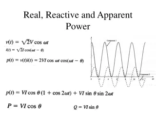
Real, Reactive, and Apparent Powers. In AC circuits, energy storage elements such as inductance and capacitance may result in periodic reversals of the direction of energy flow.

E N D
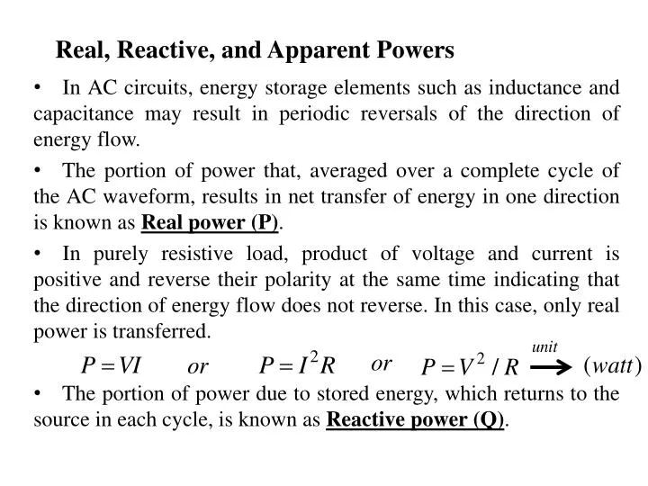
Real, Reactive, and Apparent Powers In AC circuits, energy storage elements such as inductance and capacitance may result in periodic reversals of the direction of energy flow. The portion of power that, averaged over a complete cycle of the AC waveform, results in net transfer of energy in one direction is known as Real power (P). In purely resistive load, product of voltage and current is positive and reverse their polarity at the same time indicating that the direction of energy flow does not reverse. In this case, only real power is transferred. The portion of power due to stored energy, which returns to the source in each cycle, is known as Reactive power (Q).
Real, Reactive, and Apparent Powers …… In purely reactive loads voltage and current are 90 degrees out of phase. For half of each cycle, the product of voltage and current is positive, but on the other half of the cycle, the product is negative, indicating that on average, exactly as much energy flows toward the load as flows back. As a result no net energy flow/transfer to the load over one periodic cycle. Apparent power (S)is the product of the root-mean-square of voltage and current or total power is also called apparent power.
How to control Reactive Power • Conventionally, capacitors are considered to generate reactive power and inductors to consume it. If a capacitor and an inductor are placed in parallel, then the currents flowing through the inductor and the capacitor tend to cancel rather than add. • This is the fundamental mechanism for controlling the power factor in electric power transmission; capacitors (or inductors) are inserted in a circuit to partially cancel reactive power 'consumed' by the load.
Chapter 2 Power Generation AC Voltage Generation There are basically two physical laws that describe how electric power systems work. 1st law (Faraday’s Law)has to do with generating a voltage from a changing magnetic field and 2nd law has to do with a current flowing through a wire creating a magnetic field. Faraday’s Law represents the phenomena behind how electric motors turn and how electric generators produce electricity and this law is the foundation for electric power systems.
AC Voltage Generation …….. Faraday’s Law states, “A voltage is produced on any conductor in a changing magnetic field.” Figure 2.1. A coil shows the flux linkage. The total flux linkage are obtained by adding the fluxes linkage each turn.
AC Voltage Generation …….. • Generators, use a spinning magnet (i.e., rotor) next to a coil of wire to produce voltage. This voltage is then distributed throughout the electric power system. • All generators have coils of wire mounted on stationary housings, called stators, where voltage is produced due to the magnetic field provided on the spinning rotor. • The amplitude of the generator’s output voltage can be changed by changing the strength of rotor’s magnetic field.
AC Voltage Generation …….. • Single phase AC voltage generation • Placing a coil of wire (i.e., conductor) in the presence of a moving magnetic field produces a voltage. • Changing the rotor’s speed changes the frequency of the sine wave. • Similarly by increasing the number of turns (loops) of conductor or wire in the coil increases the resulting output voltage.
AC Voltage Generation …….. • Three-Phase ac Voltage Generation • When three coils are placed in the presence of a changing magnetic field, three voltages are produced. • The coils are spaced 120 degrees apart in a 360 degree circle. 1200 1st 2nd 3rd
AC Voltage Generation …….. • The Single/three-Phase AC Generator • Large and small generators that are connected to the power system have three basic components: • Stator • Rotor • Exciter
AC Voltage Generation …….. • The Stator • A three-phase ac generator has three single-phase windings. • These three windings are mounted on the stationary part of the generator, called the stator. • These windings are physically spaced so that the changing magnetic field present on each winding is 120° out of phase with the other winding.
AC Voltage Generation …….. Stator Windings Rotor Rotor field winding
AC Voltage Generation …….. • The Rotor • The rotor is the center component that when turned moves the magnetic field. A rotor could have a permanent magnet or an electromagnet. • Large power plant generators use electromagnets so that the magnetic field can be varied. Varying the magnetic field strength of the rotor enables generation control systems to adjust the output voltage according to load demand and system losses.
AC Voltage Generation …….. • Ampere’s and Lenz’s Law (Physical Law #2) • The second basic physical law that explains how electric power systems work is the fact that current flowing in a wire produces a magnetic field. Ampere’s and Lenz’s law states that “a current flowing in a wire produces a magnetic field around the wire.” • This law describes the relationship between the production of magnetic fields and electric current flowing in a wire. In essence, when a current flows through a wire, a magnetic field surrounds the wire.
AC Voltage Generation …….. • Electromagnets • Applying a voltage (e.g., battery) to a coil of wire produces a magnetic field. The coil’s magnetic field will have a north and a south pole as shown in Figure 2-4. • Increasing the voltage or the number of turns in the winding increases the magnetic field. • Conversely, decreasing the voltage or number of turns in the winding decreases the magnetic field. • Slip rings are electrical contacts that are used to connect the stationary battery to the rotating rotor.
AC Voltage Generation …….. • The Exciter • The voltage source for the rotor, which eventually creates the rotor’s magnetic field, is called the exciter, and the coil on the rotor is called the field. • Most generators use slip rings to complete the circuit between the stationary exciter voltage source and the rotating coil on the rotor where the electromagnet produces the north and south poles.
AC Voltage Generation …….. • When load is added to a generator’s stator windings reduces rotor speed because of the repelling forces between the stator’s magnetic field, and the rotor’s magnetic field since both windings have electrical current flowing through them. • Conversely, removing load from a generator increases rotor speed. Therefore, the mechanical energy of the prime mover that is responsible for spinning the rotor must be adjusted to maintain rotor speed or frequency under varying load conditions.