Download
1 / 33
330 likes | 450 Views
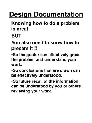
Design Documentation in ME 2110. Jeffrey Donnell MRDC 3104 894-8568 June, 2010. Agenda. What reports are for Format and information in technical reports Quick tips on presentations Our expectations for drawings How to integrate drawings and discussion. What you will do in ME 2110.

E N D
Design Documentationin ME 2110 Jeffrey Donnell MRDC 3104 894-8568 June, 2010
Agenda • What reports are for • Format and information in technical reports • Quick tips on presentations • Our expectations for drawings • How to integrate drawings and discussion J. Donnell / ME 2110 2010
What you will do in ME 2110 • Design and evaluate devices. • Document these designs using drawings. • Drawings should be computer-prepared • All design illustrations should represent your work • Characterize and evaluate the designs in written reports. J. Donnell / ME 2110 2010
Technical Communication—IFigures • Drawings display designs • Flowcharts display sequences of events • Tables display data • Graphs show comparisons • Matrices display decision criteria • Specification Sheets display evaluation criteria J. Donnell / ME 2110 2010
Technical Communication—IIDescribing Figures • What is shown? • What is important in the figure or table? • What does this system do? • What does this matrix help you to do? J. Donnell / ME 2110 2010
Reports present accomplishments Accomplishments are tangible: • A device (shown in a drawing) • A plan for solving a problem (shown in flowcharts and tables) J. Donnell / ME 2110 2010
Reports do not present administration • Team meetings • Brainstorming sessions • Concepts that were discussed but not drawn J. Donnell / ME 2110 2010
Reports require teamwork Team members must take charge of: • Text • Drawing • Quality • Coordinate figure numbers with citations • Proofread the document • Verify that page design is appropriate • Verify that the document is complete J. Donnell / ME 2110 2010
Typical Report Sections • Abstract • Introduction • Overview • As appropriate • Discussion • As appropriate • Conclusions J. Donnell / ME 2110 2010
Abstract • State Objective. • State Result. (Use numbers when available) • State Evaluation / Recommendation (such as lessons learned) • List Report Contents. Do not use figures in the Abstract J. Donnell / ME 2110 2010
Introduction • State the assigned task. • Customer Needs • Overall Product Function • Define the design challenges. • State what is presented in the report. J. Donnell / ME 2110 2010
Overview (for water heater report) Design Overview • Display and describe drawings of the selected design (for reports on large project) Planning Presentation • Display and describe Planning Tools Concept / Evaluation Presentation • Display and describe alternatives and evaluation tools J. Donnell / ME 2110 2010
Discussion Justification: How was the design selected? • Present and describe alternatives and evaluation. • Present and describe planning tools. OR Analysis: Did the design perform as expected? • Report system performance. • Account for failures and for successes. J. Donnell / ME 2110 2010
Conclusions • Restate the project task. • Restate the result and evaluation. J. Donnell / ME 2110 2010
Displaying Illustrations • Make your own drawings If an illustration is not original, you will be in trouble • Label the drawings • Number the figures • Provide captions • Cite and describe figures: “Figure 3 shows…..” J. Donnell / ME 2110 2010
How to display information in drawings J. Donnell / ME 2110 2010
Overview Drawings Drawing Labels Number with Caption The Leatherman Tool Group Figure 1. Overview of Leatherman SuperTool J. Donnell / ME 2110 2010
Subsystem Drawings BLADE END Drawings Labels Number with Caption LANYARD ATTACHMENT The Leatherman Tool Group Figure 2. Pliers Operation J. Donnell / ME 2110 2010
Detail drawings isolate components Drawing Label Number with Caption The Leatherman Tool Group Figure 3. Hard Wire Cutter Location J. Donnell / ME 2110 2010
Formal Figure Description See also section 9.1.3 of the book J. Donnell / ME 2110 2010
Describing Figures Description Statements 1) Citation 2) Objective 3) Listing of labeled features 4) Explanation of operation 5) Discussion (as needed) State potential challenges or actual results J. Donnell / ME 2110 2010
A fully labeled drawing is shown Figure 9.3 An Air Catapult J. Donnell / ME 2110 2010
The Figure is described 1 2 3 4 Figure 9.3 is a concept drawing of an air powered catapult. It is used to hurl tennis balls to the scoring zone of the design tournament field. The tennis balls are initially placed on a launch plate, which is connected to a hinge by two lever arms. Two pneumatic actuators are attached to these arms and are anchored to a base plate. Hoses connect these actuators to a T-Valve, which is connected to an air reservoir through a solenoid valve. The solenoid valve is connected to a controller box, which is not shown. To fire this catapult, the controller sends a signal to the solenoid valve. The valve opens to allow a burst of pressurized air to flow from the reservoir to the pneumatic actuators. The actuators extend, thereby forcing the lower arms and platform upward. This motion hurls the tennis ball towards the target. J. Donnell / ME 2110 2010
Labels coordinate with text discussion J. Donnell / ME 2110 2010
Figure 9.3 An Air Catapult Figure 9.3 is a concept drawing of an air powered catapult. It is used to hurl tennis balls to the scoring zone of the design tournament field. The tennis balls are initially placed on a launch plate, which is connected to a hinge by two lever arms. Two pneumatic actuators are attached to these arms and are anchored to a base plate. Hoses connect these actuators to a T-Valve, which is connected to an air reservoir through a solenoid valve. The solenoid valve is connected to a controller box, which is not shown. To fire this catapult, the controller sends a signal to the solenoid valve. The valve opens to allow a burst of pressurized air to flow from the reservoir to the pneumatic actuators. The actuators extend, thereby forcing the lever arms and platform upward. This motion hurls the tennis ball towards the target. J. Donnell / ME 2110 2010
Information Resources http://www.me.gatech.edu/undergraduate/microsoft_tools.shtml (A collection of tips for using Microsoft Word and PowerPoint with Excel, AutoCAD, and Matlab) J. Donnell / ME 2110 2010
Description ofPlanning Tools See also section 2.2 of the book J. Donnell / ME 2110 2010
Planning Tool Description • Cite the tool • State what the tool helps designers do • Call out significant entries (Cust Needs at left, Eng Char at top, Importance on the side, Strong relationship between…..) • State how it impacts your work J. Donnell / ME 2110 2010
House of Quality for Personal Transporter J. Donnell / ME 2110 2010
Description of HOQ(first of four paragraphs) (2) In order to thoroughly define the problems that a personal human transporter must address, (1) the House of Quality shown in Figure 1 was developed. (3) The column on the left lists the customer needs, which are ranked on an importance scale of 1 to 10. The top row displays the engineering requirements that have been identified at this point in the project. The most important customer needs are “Safe Operation,” “Ease of Use,” “Reliability,” and “Terrain Robustness,” which are ranked 10 and 9 in importance. J. Donnell / ME 2110 2010
House of Quality for Personal Transporter (2) In order to thoroughly define the problems that a personal human transporter must address, (1) the House of Quality shown in Figure 1 was developed. (3) The column on the left lists the customer needs, which are ranked on an importance scale of 1 to 10. The top row displays the engineering requirements that have been identified at this point in the project. The most important customer needs are “Safe Operation,” “Ease of Use,” “Reliability,” and “Terrain Robustness,” which are ranked 10 and 9 in importance. J. Donnell / ME 2110 2010
House of Quality for Personal Transporter Based on this analysis of the problem, the design presented here addresses community acceptance in the requirement of “Sidewalk Compatibility,” and it addresses safety in the requirements of “Terrain Stability” and “Ground Clearance.” J. Donnell / ME 2110 2010