Download
1 / 35
350 likes | 498 Views
Noise Isolation. Keeping the Gremlins Out. How noise gets into your circuits. Key Characteristics of the noise source. Voltage. ‘High’ voltage. Strong electric field. Capacitive coupling. ‘High dV/dt. Capacitive coupling. Current. ‘High’ current. Strong magnetic field.

E N D
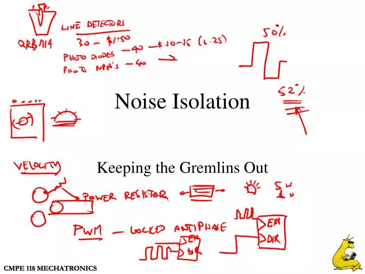
Noise Isolation Keeping the Gremlins Out
Key Characteristics of the noise source Voltage ‘High’ voltage Strong electric field Capacitive coupling ‘High dV/dt Capacitive coupling Current ‘High’ current Strong magnetic field Inductive coupling Frequency ‘High’ frequency Radiative coupling Radiation Distance from the victim Distance = 0 Direct contact Conductive coupling Distance > wavelength Probably Radiative Not For Us 0 < Distance < Wavelength Capacitive or Inductive
Key Characteristics of the noise source Voltage Current Frequency Distance from the victim
What is the most likely coupling mechanism for Fluorescent light noise Capacitive High Voltage Arc welding noise Inductive High Current Digital clock noise Capacitive High dv/dt
What is the most likely coupling mechanism for Fluorescent light noise Arc welding noise Digital clock noise
Conductive coupling Motor Sensor
More conductive coupling +12V +5V
How should I wire these up? 12V 7.5V + G + G Motor + G HC11 + G + G Sensor
Identifying characteristics of conductive coupling Metallic contact required Unaffected by people or cable movement Non-zero average value for the waveform Techniques to reduce conductive coupling Break the conductive contact Use filtering
Identifying characteristics of conductive coupling Metallic contact required Unaffected by people or cable movement Techniques to reduce conductive coupling Break the conductive contact Use filtering
Capacitively coupled noise Simplified circuit Coupling capacitance
Physical Representation of capacitively coupled noise
Equivalent circuit for capacitively coupled noise If If
Reducing Capacitively coupled noise Shield Position the shield to intercept the noise current Connect the shield to return the noise current to the source How many connections to the shield are required?
Summary of capacitive noise reduction techniques Reduce capacitive noise coupling by 1. Reducing coupling capacitance 2. Reducing circuit impedance 3. Using shielding Capacitive shielding requires 1. Proper shield location 2. Correct shield connection
Summary of capacitive noise reduction techniques Reduce capacitive noise coupling by Capacitive shielding requires
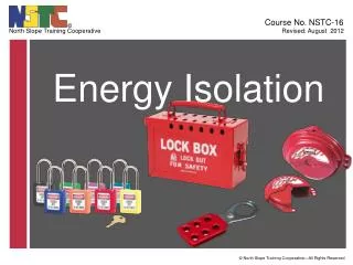
Isolation Why do you need it? Conductive noise Large voltage differential Provide fault isolation (Safety) Minimize leakage currents How do you get it? Magnetic coupling Optical coupling
Isolation Why do you need it? How do you get it?
Create a design to connect L-298 H-Bridge 68HC11 PS2501 Opto-Isolator