Download
1 / 43
430 likes | 518 Views
Goal Derive the radar equation for an isolated target. Measurement of the echo power received from a target provides useful information about it. The radar equation provides a relationship between the received power, the characteristics of the target, and characteristics of the radar itself.

E N D
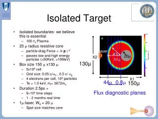
Goal Derive the radar equation for an isolated target Measurement of the echo power received from a target provides useful information about it. The radar equation provides a relationship between the received power, the characteristics of the target, and characteristics of the radar itself. • Steps in deriving the radar equation for an isolated target: • Determine the radiated power per unit area (the power flux density) incident on the target • Determine the power flux density scattered back toward the radar (the radar cross section) • Determine the amount of power collected by the antenna • (the antenna effective area).
Consider an isotropic antenna An antenna that transmits radiation equally in all directions Power flux density (S, watts/m2) at radius r from an isotropic antenna (1) Where Pt is the transmitted power
The gain function The gain* is the ratio of the power flux density at radius r, azimuth q, and elevation f for a directional antenna, to the power flux density for an isotropic antenna radiating the same total power. (2) So from (1) (3) *strictly speaking, the gain also incorporates any absorptive losses at the antenna and in the waveguide to the directional coupler
What does the gain function look like? Note elevation and azimuth angle scales Gain in dB
The gain function in 2D Note that the width of the main beam is proportional to wavelength and inversely proportional to the antenna aperture Therefore: Large wavelength radars = big antenna Small wavelength radars = small antenna for same beam width Beam width (3 db down from peak) 10 cm 0.8 cm
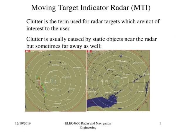
Problems associated with sidelobes Horizontal “spreading” of weaker echo to the sides of a storm… Echo from sidelobe is interpreted to be in the direction of the main beam, but the magnitude is weak because power in sidelobe is down ~ 25 db.
Problems associated with sidelobes Vertical “spreading” of weaker echo to the top of a storm… Echo from sidelobe is interpreted to be in the direction of the main beam, but the magnitude is weak because power in sidelobe is down ~ 25 db.
A way to reduce sidelobes: Tapered Illumination • Three effects: • A reduction in sidelobe levels • (desirable) • A reduction in maximum power • gain (undesirable) • An increase in beamwidth • (undesirable) Example: Parabolic illumination to zero at reflector edge for a circular paraboloid antenna leads to a sidelobe reduction of 7 db, a gain reduction of 1.25 db, and an increase in beamwidth of 25%
The shape of beam depends on the shape of an antenna For meteorological applications, the circular paraboloid antenna is most commonly used – beam has no preferred orientation
Practical Antenna Beamwidths: The smaller the antenna beamwidth, the better the angular resolution. The smaller the antenna beamwidth, the bigger the antenna. The smaller the antenna beamwidth, the longer it takes to scan a volume. Most meteorological radars (e.g. NEXRADS) use beams of ~ 1o width Suppose you wish to scan 360o and 20 elevations to completely sample Deep storms in the area. There are 360 20 = 7200 1o elements to be scanned. Required dwell time for a sufficient number of pulses to average per beam width is about 0.05 seconds. Total time = 7200 0.05 = 360 sec = 6 minutes When considering evolution of convective storms, 6 min is a long time!
(3) Some typical values: Gain = 10,000 (40 db) Transmitted Power = 100,000 Watts Target is at 100 km range Incident Power Flux Density = 8 x 10⁻³ Watts/m2
Radar cross section: Ratio of the power flux density scattered by the target in the direction of the antenna to the power flux density incident on the target, both measured at the radius of target. (4) PROBLEM: We don’t measure Sscattered at r, we measure it at radar Ratio of power flux density received at the antenna (Sr) to the power flux density incident on the object at radius (r) from the antenna (5) The 4pr2 is required because the backscattered power flux density is measured at the antenna, not at the location of the object, where it would be greater by 4pr2
In general, the radar cross section of an object depends on: • Object’s shape • 2) Size (in relation to the radar wavelength) • 3) Complex dielectric constant and conductivity of the material • (related to substances ability to absorb/scatter energy) • 4) Viewing aspect
Radar cross section of a sphere (e.g. small raindrop) Note axes: a is sphere radius Rayleigh region: a < l/2 p l/6
Radar cross section (5) Recall from before the power flux density incident on an object (3) Substituting: Some typical values: Gain = 10,000 (40 db) Transmitted Power = 100,000 Watts Target is at 100 km range Radar cross section = 1 m2 Power Flux Density at the antenna = 6.3 x 10⁻¹⁴ Watts/m2!! (6)
(6) Power received at antenna: Where Ae is the effective Area of the antenna (7) From antenna theory - Relationship between gain and effective area: (8)
Substituting for Ae in (7): (9) Which we will write as: (10) radar characteristics target characteristics constant This is the radar equation for a single isolated target (e.g. an airplane, a ship, a bird, one raindrop, the moon…)
(10) radar characteristics target characteristics constant Written another way in terms of antenna effective area: (11) radar characteristics target characteristics constant What do these equations tell us about radar returns from a single target?
Goal Derive the radar equation for an distributed target Distributed target: A target consisting of many scattering elements, for example, the billions of raindrops that might be illuminated by a radar pulse. Contributing region: Volume consisting of all objects from which the scattered microwaves arrive back at the radar simultaneously. Spherical shell centered on the radar - Radial extent determined by the pulse duration (half the pulse duration) -Angular extent determined by the antenna beam pattern
Pulse volume Azimuthal coordinate: q The beamwidth in the azimuthal direction: rQ, where Q is the arc length between the half power points of the beam Elevation coordinate: f The beamwidth in the elevation direction: rF , where F is the arc length between the half power points of the beam The cross sectional area of beam: Contributing volume length = half the pulse length: Approximate volume of contributing region: (12)
Consider the NEXRAD radar Pulse duration t = 1.57 ms Angular circular beamwidth = 0.0162 radians If the concentration of raindrops is a typical 1/m3, then the pulse volume contains 520 million raindrops!
Note that the “pulse volume” is only an approximation. Recall the antenna beam pattern: About half of the transmitted power falls outside the 3 db cone. In addition, the Gain function is such that the particles on the beam axis receive more power than those off axis, so the illumination in the pulse volume is not uniform. CAVEATS
The radar cross section of a distributed target • Assumptions: • The radial extent (h/2) of the contributing region is small compared to the • range (r) so that the variation of Sinc across h/2 can be neglected. (good assumption) • Sinc is considered uniform across the conical beam and zero outside – the spatial variation of the gain function can be ignored. (not good, but we are stuck with this one) • Scattering by other objects toward the contributing region must be small so that interference effects with the incident wave do not modify its amplitude. (good for wavelengths > 3 cm) • 4) Scattering or absorption of microwaves by objects between the radar and contributing region do not modify the amplitude of Sinc appreciably. (good for wavelengths > 3 cm)
Is the radar cross section of a distributed target equal to the sum of the radar cross sections of the individual particles that comprise the distributed target?
Consider two same-sized particles that are n wavelengths + ¼ wavelength apart n wavelengths + ¼ wavelength Incident waves scattered by each particle will be ½ wavelength out of phase since waves must travel out and back DESTRUCTIVE INTERFERENCE: NET AMPLITUDE = 0 Consider two same-sized particles that are n wavelengths + ½ wavelength apart n wavelengths + ½ wavelength Incident waves scattered by each particle will be an integer wavelength apart and in phase since waves must travel out and back CONSTRUCTIVE INTERFERENCE: NET AMPLITUDE = LARGE
Is the radar cross section of a distributed target equal to the sum of the radar cross sections of the individual particles that comprise the distributed target? Not clear, since there are destructive and constructive interference effects occurring within the backscattered waves from the array of particles. Let’s look at the problem mathematically to determine if the equation above is true…
Consider a radar transmitting a wave whose electric field is represented as: Eo = amplitude = 2pft = angular frequency (13) The wave incident on the jth particle at range rj is: (14) The backscattered electric field from the jth particle, when arriving at the radar, will be proportional to the amplitude of the incident wave, and inversely proportional to the range (15)
Total backscattered field is the phasor sum of the contributions from all of the individual scattering objects: Rewrite this equation using the relationship: (16) The power flux density returned to the radar is proportional to the square of the Electric field, where the proportionality constant is Z0, the characteristic impedence of free space. complex conjugate Permeability (17) Permittivity
Substituting (1) into (2) (18) (19) Which can be broken up for terms where j = k and those where j k (20) Interference terms
(20) Interference terms Value of double summation depends on the scattering properties of the individual objects and their positions. If particles are randomly distributed, then the phase increments are randomly distributed. If we assume particles to “reshuffle” to a new random distribution between successive pulses, then the average of the double sum term over a number of pulses must approach zero, since rj – rk will change for all particles
The average power flux density over a number of pulses is therefore: (21) Let’s suppose there is only one particle. Then: (22) Applying the definition of the radar cross section: (23) Since the radar cross section is related to the proportionality constant r, we can write: (24) (25)
Implication of the above mathematical exercise To eliminate interference effects, and obtain a true estimate of the average power flux density returned to the radar, we must average the power flux density from a sufficient number of pulses. How many pulses are sufficient? It depends on application… NCAR S-POL radar often uses 64 pulse average, leading to an average over a sweep of one beam width with a rotation rate of 8°/sec Number of pulses in average also determines Doppler velocity resolution, as we shall see in a later chapter…
(26) Radar equation for single target: (10) Radar equation for a distributed target: (27)
Definition of the “radar reflectivity”, h Where Vc is the contributing volume (28) Units of radar reflectivity: Recall the equation for the contributing volume: (12) Substituting (12) into (28), and (28) into the radar equation (11): (29)
(30) The above equation applies for a uniform beam. For a Gaussian beam, a correction term 2ln(2) has to be added (31) target characteristics radar characteristics
Note: The returned power for a single target varies as r-4. (11) radar characteristics target characteristics constant The returned power for a distributed target varies as r-2 (31) radar characteristics target characteristics constant Why?
Note: The returned power for a single target varies as r-4. (11) radar characteristics target characteristics constant The returned power for a distributed target varies as r-2 (31) radar characteristics target characteristics constant Reason: As contributing volume grows with distance, more targets are added. Number of targets added is proportional to r2, which reduces the dependence of the returned power from r-4 to r-2.
Next task: Derive the radar equation for weather targets