Download
1 / 122
1.22k likes | 1.23k Views
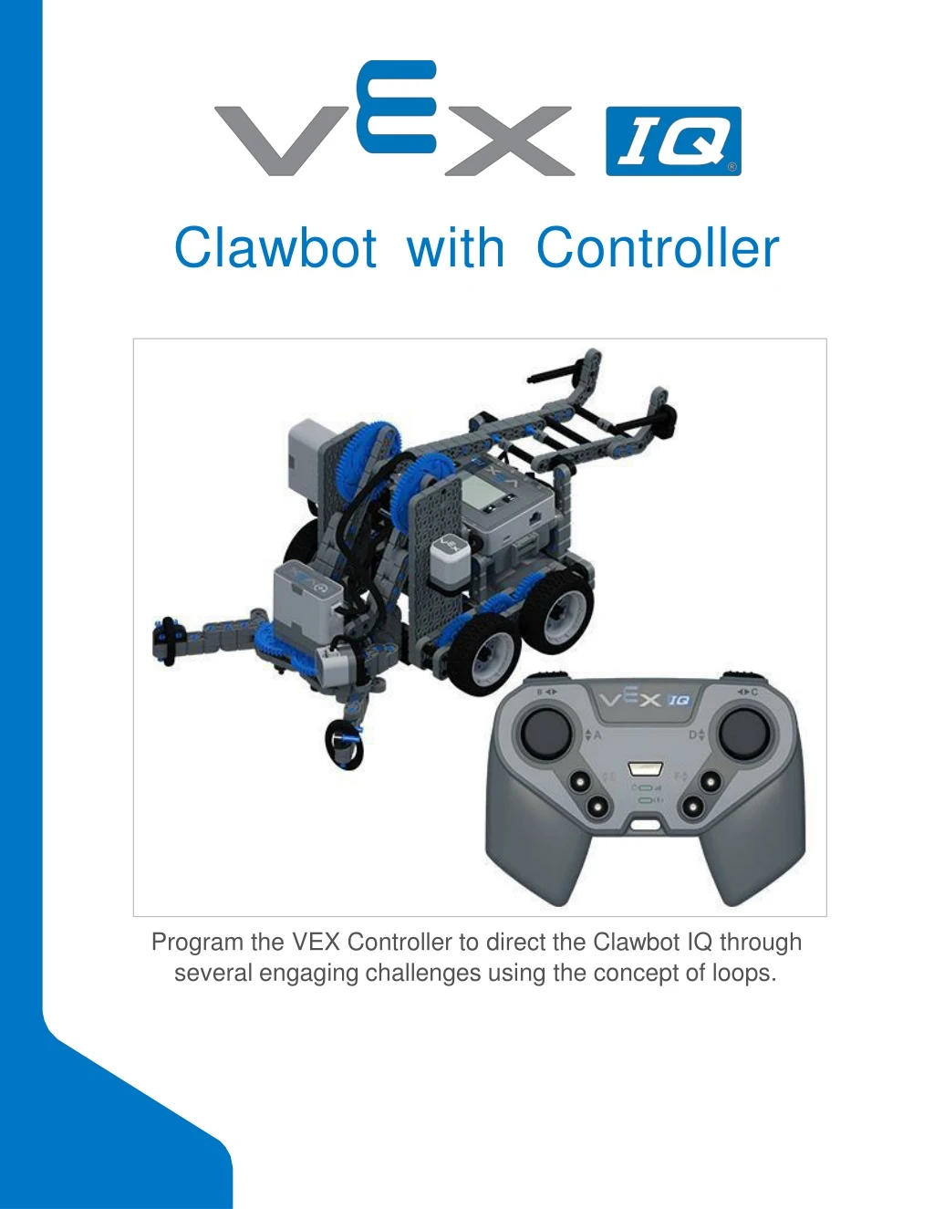
Clawbot with Controller. Program the VEX Controller to direct the Clawbot IQ through several engaging challenges using the concept of loops. Discover new hands-on builds and programming opportunities to further your understanding of a subject matter.

E N D
Clawbot with Controller Program the VEX Controller to direct the Clawbot IQ through several engaging challenges using the concept ofloops.
Discover new hands-on builds and programming opportunities to further your understanding of a subjectmatter.
The Completed Look of the Build The completed Clawbot IQbuild. This robot is designed so that it can be built quickly and drive around either autonomously or with the Controller in a short amount oftime.
BuildInstructions-Drivetrain+ Distance • Build InstructionsSummary • Drivetrain + Distance Building Instructions (19steps): • Right Wheel: steps 1 to6 • Left Wheel: steps 7 to12 • Distance Sensor: steps 13 to19 • Building Tips for AllSteps: • The section at the top of the step shows important information for the build. The first number under the image of the part (1x, 2x, 4x, etc) is the number of that piece you will need in this step. The next information under the part image is the size and description of the partneeded. • The finished step is illustrated in the box in the lower rightcorner.
o Play close attention to the green lines in the step images. They will indicate how the parts should beconnected.
Step 1: Count all pieces before starting your build and have them readily available. Each team member should find the pieces for their section. Step 2: When adding the 4x Pitch Shaft, twist the pitch shaft to check for tension while turning. If it spins freely, it is not properly inserted into themotor.
Step 5: Make sure the gears fit together properly before locking the 2x12 Beam inplace. Step 6: After attaching the wheels, twist the wheel that has the shaft going into the motor. If the wheel spins freely and without tension, the 4x Pitch Shaft has slipped out ofplace.
Step 8: When adding the 4x Pitch Shaft, twist the pitch shaft to check for tension while turning. If it spins freely, it is not properly inserted into themotor.
Step 11: Make sure the gears fit together properly before locking the 2x12 Beam inplace. Step 12: After attaching the wheels, twist the wheel that has the shaft going into the motor. If the wheel spins freely and without tension, the 4x Pitch Shaft has slipped out ofplace.
Step 14: Make sure the Gyro is placed the correct way to allow correct cableaccess.
Step 19: When attaching the Distance Sensor, do not push on either of the two mesh covered openings. This will damage the sensor. Ensure the sensor is placed in the correct way to allow cableaccess.
BuildInstructions-RobotFrame • Build InstructionsSummary • Robot Frame Building Instructions (22steps): • Cargo Holder: steps 20 to28 • Arm Base: steps 29 to41 • Building Tips for AllSteps: • The section at the top of the step shows important information for the build. The first number under the image of the part (1x, 2x, 4x, etc) is the number of that piece you will need in this step. The next information under the part image is the size and description of the partneeded. • The finished step is illustrated in the box in the lower rightcorner.
o Play close attention to the green lines in the step images. They will indicate how the parts should beconnected.
Step 33: Make sure the Bumper Switch is placed in the correct way to allow cableaccess.
Step 36: Make sure your Smart Motor is oriented in the correct direction (the hole for the shaft is on thebottom).
Step 38: Make sure that the Touch LEDis placed in the correct way to allow cableaccess.
Step 39: The orange arrows mean spin the buildaround. Step 40: Instead of individual parts, the completed sections of the build needed are shown in the section at the top. When adding the Step 37 Assembly, twist the pitch shaft to check for tension while turning. If it spins freely, it is not properly inserted into themotor.
Step 41: Instead of individual parts, the completed sections of the build needed are shown in the section at the top. The orange arrows mean spin the buildaround.
BuildInstructions-Arm • Build InstructionsSummary • Arm Building Instructions (19steps): • Arm: steps 42 to60 • Building Tips for AllSteps: • The section at the top of the step shows important information for the build. The first number under the image of the part (1x, 2x, 4x, etc) is the number of that piece you will need in this step. The next information under the part image is the size and description of the partneeded. • The finished step is illustrated in the box in the lower rightcorner.
o Play close attention to the green lines in the step images. They will indicate how the parts should beconnected.
Step 48: Make sure the gears fit together properly before moving on to the nextstep. Step 49: Turn one of the black shafts in the center of the gear to make sure they are together and both turn at the same time before adding the 4x4Plate.
Step 56: Instead of individual parts, the completed sections of the build needed are shown in the section at the top.
Step 59: Instead of individual parts, the completed sections of the build needed are shown in the section at the top. Step 60: Make sure your Smart Motor is are oriented in the correct direction (the hole for the shaft is on theright). After adding motor, turn one of the gears to check for tension while turning. If it spins freely, it is not properly inserted into themotor.
BuildInstructions-Claw • Build InstructionsSummary • Claw Building Instructions (22 steps): • Claw: steps 61 to82 • Building Tips for AllSteps: • The section at the top of the step shows important information for the build. The first number under the image of the part (1x, 2x, 4x, etc) is the number of that piece you will need in this step. The next information under the part image is the size and description of the partneeded. • The finished step is illustrated in the box in the lower rightcorner.
o Play close attention to the green lines in the step images. They will indicate how the parts should beconnected.
Step 67: Make sure that the 100mm Travel Tire fits snugly in the grove of the 2x Wide, ½ CornerConnector. Step 68: The orange arrows mean spin the buildaround.