Download
1 / 17
170 likes | 287 Views
IPM status and plans Yellow vertical detector has extremely low coupling to beam and to signal-gating grid. It also has improved resolution due to reduced channel spacing. (Dave Kipp) A. Anode circuit board and MCP in an rf enclosure. Electron signal passes

E N D
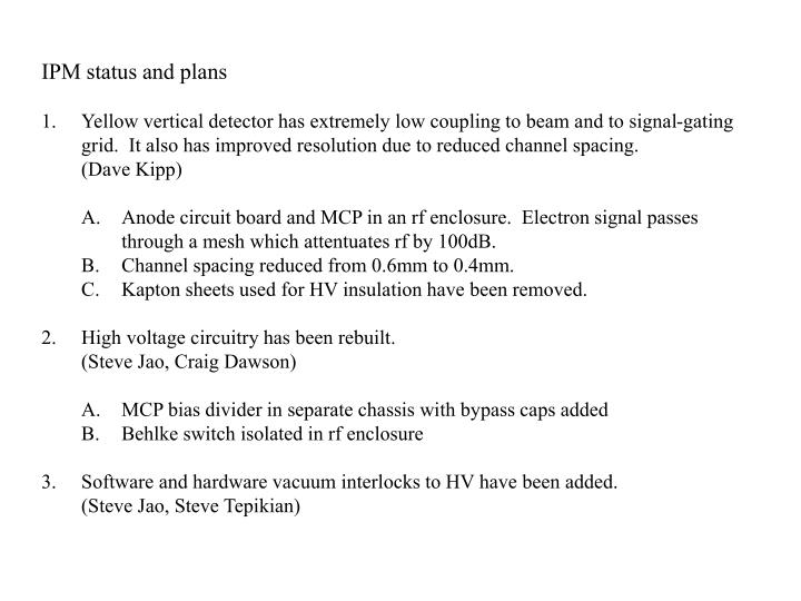
IPM status and plans Yellow vertical detector has extremely low coupling to beam and to signal-gating grid. It also has improved resolution due to reduced channel spacing. (Dave Kipp) A. Anode circuit board and MCP in an rf enclosure. Electron signal passes through a mesh which attentuates rf by 100dB. B. Channel spacing reduced from 0.6mm to 0.4mm. C. Kapton sheets used for HV insulation have been removed. High voltage circuitry has been rebuilt. (Steve Jao, Craig Dawson) A. MCP bias divider in separate chassis with bypass caps added B. Behlke switch isolated in rf enclosure Software and hardware vacuum interlocks to HV have been added. (Steve Jao, Steve Tepikian)
Collector board and MCP, together with all the feedthroughs, are isolated in an rf enclosure. Electrons enter colllector through mesh rated to attentuate rf by 100dB.
Sweep electrode held on ceramic standoffs. Signal connections are bare wires with fish-spine beads.
New design greatly reduces coupling between signal-gating grid and anode. Yellow horizontal Yellow vertical Bucket #1. There is no noise from gate firing. Noise burst when gate fires. Bunch in bucket #1 Six bunch fill on Friday afternoon.
Old HV distribution box. Divider chain for MCP biasing. This circuitry was picking up noise from the Behlke switch. It is now in a separate enclosure. Pulse monitoring circuit and Behlke switch. The monitoring circuit was picking up transients from the switch. The switch is now in an rf enclosure.
Yellow horizontal Yellow vertical Top trace is the signal gate opening for one turn. The time constant for the gate voltage ramping back up is much shorter in the vertical detector from improvements made in the electronics. The signal is gated off in about 20ms in vertical compared with >80ms in horizontal.
Hardware HV interlock Power supplies were interlocked to vacuum gauge to latch off at 1e-6torr. Yellow vertical with new MCP is still gassy and keeps tripping off on ramp with 10s measurement intervals.
Friday Steve added a software interlock. This turns off sweep voltage at 1e-7torr and turns it back on at 1e-8torr. The hardware interlock is still in place for equipment protection. This is ramp from this morning showing that 8 measurements were lost instead of the last half of the ramp.
Consider scatter in measured emittance. I analyze a three hour period during Fill 9358, 15:30 Dec. 7 to 8:30 Dec. 8.
A line is fitted to the emittance values and a table is generated of differences between measured values and the value of the fit. These numbers added to the average emittance for this three hour period are plotted. The rms of the differences is 0.393 or 2.7%.
Statistical noise floor. The scatter in consecutive measurements is limited by statistics. I did a Monte Carlo calculation where N numbers were pulled randomly from a gaussian parent distribution. For each sample a gaussian was fit to the data. After many measurements the average and standard deviation of the sigmas was calculated. Plotted here are the values of SD/AVG vs. N. A sample of 1,000 electrons has a limit of ±2% scatter and a sample of 10,000 points has a limit close to ±1%.
Estimated signal in yellow detectors. In yellow vertical the base pressure is 6 x10⁻¹⁰ torr. This is assumed to be H2 and He. During measurement the pressure rises to 1.3 x 10⁻⁹ torr. I assume this is water. Single bunch intensities were ~0.8 x 10⁹ during these fills. Using these numbers and the measured cross sections from CERN report 'Principles of Operation of Multiwire Proportional and Drift Chambers' by F. Sauli (77-09), I estimate that each gold bunch in the IPM chamber produces about 1,000 electrons. We average 100 bunches so each measurement is from 105 electrons. Average pressure in horizontal is about 10% of vertical. From graph in last slide the difference in measurement-measurement scatter should be much less than 1% between the two detectors based on signal sizes. Difference is 1.2% with Yellow vertical being quieter. The same analysis of fill #9364 gives 1rms scatter of Vertical=2.5%, Horizontal=2.9%.
Summary The yellow vertical IPM and its biasing electronics have been rebuilt. The coupling between the signal- gating grid and the anode has been greatly reduced and the signal gating off time is much shorter. Huge amounts of kapton sheeting was removed. HV conditioning time eliminated from hours at vacuum. The measurement-measurement scatter in yellow vertical is smaller then yellow horizontal. Some of this difference is from the higher chamber pressure in vertical from the new MCP outgassing, however the difference appears to be larger than would be expected from the improved statistics. More analysis needs to be done here. Two levels of pressure interlocks have been added. A pressure of 10-6 torr latches off the HV power supplies. Also Steve Tepikian, on Friday, added a software interlock. When the chamber pressure reached 10-7 torr the sweep voltage is set to zero. It is reset to 6,000V when the pressure recovers to 10-8 torr. This seems to have kept Yellow vertical on in the second half of the ramp over the weekend. We are planning to rebuild all of the IPMs to this basic design during the next shutdown. Significant contributions to the IPM system have been made by: Craig Dawson Craig Rhein Jesse Fite Tom Russo Steve Jao Todd Satogata Dave Kipp Steve Tepikian Rob Michnoff Chuck Trabocchi