Download
1 / 21
210 likes | 342 Views
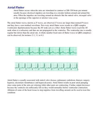
DTTB System Doppler and Flutter Character. This presentation seeks to explain some of the questions, particularly in the area of dynamic multipath DTTB character. Some questions are :. (1) What are the mechanics of Flutter ?

E N D
DTTB System Doppler and Flutter Character • This presentation seeks to explain some of the questions, particularly in the area of dynamic multipath DTTB character. Some questions are : (1) What are themechanics of Flutter ? (2) What amount of flutter or doppler freq. needs to catered for? WTD
DTTB Transmission The aspects, mechanics and impact of “Flutter” onDTTB reception WTD
DTTB TransmissionRevisiting “DOPPLER Shift” Decreased periodHence increased frequency Vt F= f + f * Vt / Vs Whistle (f) Vs Vto = Vt Explanation : While a “compression” of sound is in the air it is followed by another, but closer, aided by the speed of the train. C R C R C R C R Vt Vt Vt = Speed of train Vto Vto = Vt * cos Vs = Speed of sound ( constant ) Vto Vto = Observed speed of train f = frequency of whistle F = Observed frequency C = Compression Vto = Vt * cos Period between the “compressions” are partially modified by the speed of the train R = Rarefaction Period between the “compressions” are unmodified by the speed of the train - for approaching F= f + Cos * f * Vt / Vs Vto = o F= f - Cos * f * Vt / Vs - for departing Doppler shift WTD
The mechanics of Aircraft Flutter - Doppler Shift Va Ghost signal (doppler shifted) wfas Far RF envelope Direct signal Reflected Incident wf (wfas - wf ) Doppler shift F Fas F F = Frequency of transmission Detected video signal : Far = frequency of received signal at aircraft Direct Fas = frequency of received signal, at viewer’s TV receiver, sent from aircraft. Ghost Amplitude variation at doppler frequency Va = Speed of aircraft tg c = Speed of light (constant) Far = F - F * Cos * Va / c time Fas = Far + Far * Cos * Va / c As (F * Cos * Va / c) <<< F : Fas = F - F * Cos * Va / c + F * Cos * Va / c ie : Fas = F + sum of doppler shifts WTD
The mechanics of Aircraft Flutter - Ghost Timing Va Detected video signal : Far Direct Das Incident Ha Ghost Dar Amplitude variation at doppler frequency tg Reflected F Fas time D F Ht tg tg = in-direct path delay - direct path delay D = Direct path distance (Km) = ( Dar + Das ) / c - D / c Dar = Distance fron Tx to aircraft (Km) = ( Dar + Das - D ) / c Das = distance from aircraft to receiver (Km) tg = time to ghost from direct signal (uSec) c = Speed of light = 3 x 10^8 m/sec = 0.3Km / uSec Dar = (Ha - Ht) / Sin Das = (Ha - Ht) / Sin tg = (Dar + Das - D ) / 0.3 uSec Note : 1. When = there will be maximum reflected signal. 2. As the aircraft path is not obscured by terrain the potential for a large ghost is high. WTD
DTTB TransmissionAircraft Flutter Scenario 1 Va Far Das Dar Fas D F Fas = F - F * Cos * Va / c + F * Cos * Va / c As Cos = 0 ( = 90 degs.) tg = ( Dar + Das - D ) / 0.3 uSec Fas = F + F * Cos * Va / c Doppler shift WTD
DTTB Transmission Aircraft Flutter Scenario 2 Va Far Das Dar Fas D F Fas = F - F * Cos * Va / c + F * Cos * Va / c tg = ( Dar + Das - D ) / 0.3 uSec Doppler shift NOTE : There are competing doppler shifts. If = Fas = F ie There will be no resultant doppler shift WTD
DTTB Transmission Aircraft Flutter Scenario 3 Va Far Das Dar Fas D F Fas = F - F * Cos * Va / c + F * Cos * Va / c As (F * Cos * Va / c) = 0 ( = 90 deg.) Fas = F - F * Cos * Va / c tg = ( Dar + Das - D ) / 0.3 uSec Doppler shift WTD
DTTB Transmission Aircraft Flutter Scenario 4 Va Far Dar As the reflected path’s existence will rely upon the complex detail of the aircraft, the magnitude of the reflected signal may be low. Das Fas D F Note : If the scenario was involving a bus or a truck on a highway, a large reflection is possible. Fas = F - F * Cos * Va / c - F * Cos * Va / c tg = ( Dar + Das - D ) / 0.3 uSec Doppler shift NOTE : There are adding Doppler shifts WTD
DTTB Transmission Aircraft Flutter Scenario 5 Va Far Das Dar Fas F Db Da D tg = ( Dar + Das - (Da +Db) ) / 0.3 uSec NOTE : In this scenario, when the normal reception path is longer than the aircraft generated path, a pre-ghost with flutter will exist. Fas = F - F * Cos * Va / c + F * Cos * Va / c Doppler shift WTD
Notes on Aircraft Flutter Scenarios Notes on the Scenarios : • 3 - D environments will reduce the doppler shifts related to the angle of the aircraft to the 2- D Scenarios shown • The 2 - D scenarios shown are the worse case • Maximum reflection is likely to occur when the Incident angle equals the Reflected angle..The doppler shift is then zero. • The magnitude of the reflections when there is un-equal Incident and Reflected angle will depend upon the complex shape of the aircraft or vehicle, gain (front ,side and rear) of the receive antenna. • The magnitudes of the reflections from the aircraft have the potential of being high compared to the terrain obstructed and ground cluttered direct path. WTD
DTTB TransmissionAircraft Doppler Summary Va x 2 x 1 DOPPLER SHIFT 0 F * Va / c - x 1 - x 2 Scenario4 Scenario1 Scenario2 Scenario3 F Note : Scenario 5 is all above but with a Pre - ghost. WTD
Ghost Amplitude Variation of Aircraft Flutter Va GHOST Amplitude High This curve is an example of the possible level variations of the ghost with the position of the plane and hence with time. Indoor Antenna Outdoor Antenna Low Scenario4 Scenario1 Scenario2 Scenario3 The amplitude relationship with respect to the main direct path with time is influenced by such things as : * height of aircraft * reflection efficiency from aircraft (or vehicle) related to incident and reflected angles * receive antenna characteristics * the extent of the terrain obstruction of the main direct path. F WTD
DTTB Systems Doppler Performance Limits for current implementations 300 250 UHF 200 DOPPLERSHIFT(Hz) COFDM 2K, 3dB degrade 140 VHF - Band III COFDM 2K 100 50 0 0 100 200 300 400 500 600 700 800 900 1000 ATSC see separate curves SPEED (Km/Hr) Vehicles AIRCRAFT Over Cities COFDM implementations will inherently handle post and pre-ghosts equally within the selected guard interval. WTD
ATSC 8-VSB Doppler Performance Limits for current implementations 10 UHF VHF - Band III DOPPLERSHIFT(Hz) 8VSB, “Fast Mode”, 3dB degrade 5 8VSB 1 0 0 2 6 10 23 30 100 SPEED (Km/Hr) Vehicles Aircraft 8VSB implementations of equalisers are likely to cater for post ghosts up to 30 uSec and pre-ghosts up to 3 uSec only. WTD
DVB-T COFDM 8K Doppler Performance Limits 300 250 UHF DOPPLERSHIFT(Hz) 200 140 VHF - Band III 100 COFDM 8K mode COFDM 8K, 3dB degrade 50 COFDM 8K 0 0 100 200 300 400 500 600 700 800 900 1000 ATSC see separate curves SPEED (Km/Hr) Vehicles AIRCRAFT Over Cities COFDM implementations will inherently handle post and pre-ghosts equally within the selected guard interval. WTD
Doppler PerformanceOutcomes Outcome from scenarios : • When the Doppler shift is maximum the amplitude of the ghost is low. • When the amplitude is maximum the Doppler shift of the ghost is low. • Up to full Doppler shift with the amplitudes in the range that will affect the DTTB systems (>-15dB echo) may be common. WTD
DTTB SystemsDoppler Shift Range Doppler shift range : • Up to 160 to 250Hz doppler shift will be experienced over the UHF band. • Up to 55 to 75Hz doppler shift will be experienced over the VHF band. • Up to 20 and 70Hz doppler shift will be experienced from vehicles in urban areas in the VHF and UHF bands respectfully. WTD
DTTB TransmissionAircraft Flutter Behaviour DTTB system performance : • The COFDM 2K system will allow up to 300Hz doppler shift • The COFDM 8K system may allow up to 75Hz doppler shift • The 8VSB system may allow up to 5Hz doppler shift • before the picture and the sound is interrupted. WTD
DTTB system Laboratory Doppler Tests Doppler Echo 0 -5 -10 EchoLevel(dB) -15 COFDM -20 8-VSB -25 -500 -400 -300 -200 -100 0 100 300 500 200 400 Doppler Frequency (Hz) 8VSB standard mode (1Hz nom.) Fast mode - not shown (5Hz nom.) WTD
Aircraft Flutter & Doppler Perfomance Conclusion DTTB system performance : • The COFDM 2K system is OK for VHF and UHF reception conditions. • The COFDM 8K system is OK for VHF reception conditions. • The 8VSB system is highly susceptible to any flutter from either Aircraft or vehicles. Compiled by Wayne Dickson SMIREE MIEAust CPEng. Member SMPTE WTD