Download
1 / 28
280 likes | 388 Views
WIYN: NOAO User’s Committee October 13, 2004. Photo by Amy Eckert, Discover Magazine. Wisconsin, Indiana, Yale, NOAO. Instrumentation at WIYN. Currently supported general-use instruments MiniMosaic (4Kx4K) imager OPTIC (4Kx4K) imager [50% availability from J. Tonry]

E N D
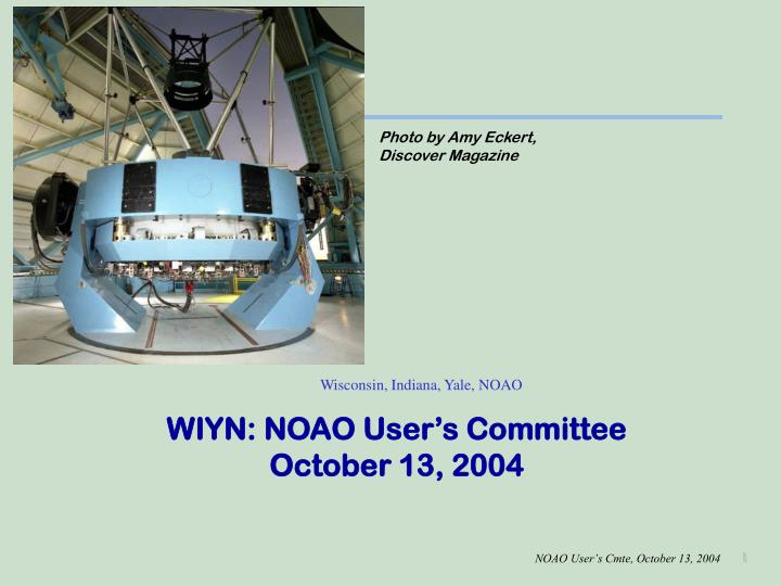
WIYN: NOAO User’s CommitteeOctober 13, 2004 Photo by Amy Eckert, Discover Magazine Wisconsin, Indiana, Yale, NOAO
Instrumentation at WIYN • Currently supported general-use instruments • MiniMosaic (4Kx4K) imager • OPTIC (4Kx4K) imager [50% availability from J. Tonry] • WTTM (2Kx2K) tip/tilt corrected imager [always on] • Hydra [always on] • Densepak • Sparsepak • Near-term upgrades • Hydra rebuilt last year for reliability and maintenance • Bench upgrades for throughput gains of 2-3X • VPH gratings (740 line in-hand; 3550 line in 6 months) • New CCD (finer pixels, faster readout, better red/blue) • Short FL, off-axis collimator
Status – Bench • Off-axis collimator design completed awaiting final consensus between project scientist and optical designer • 740 line VPH grating ready to be tested – deferred to react to CCD failures and to focus on Hydra commissioning • 3550 line VPH grating designed by Matt Bershady • R > 20,000 at 510.6 nm; optimized for 450-550 nm • glass purchased (250mm x 500mm x 30mm) • Fabrication by CSL (Belgium); delivery by December 2004 • Project web page updated Web Page • CCDs being tested (2600x4000 x 12 micron), contract with Univ of Arizona in place to thin, package, and test CCDs
Instrumentation on 2+ Year Track • WHIRC – Funded by STScI, WIYN, and (hopefully) NSF • 2Kx2K NIR imager for WTTM • 0.09” pixels for near-diffraction limited imaging • Expected availability – mid-2006 • Being built at STScI (Margaret Mexiner, Don Figer) • QUOTA – NSF funded • 8Kx8K imager with OT CCDs (OTAs) • 16 arcmin FOV • Expected availability – mid-2006 • ODI – Funding from WIYN (thus far), but NSF proposals to be written • 32Kx32K imager with OTAs • Details to follow
QUOTA and ODI ODI (2005) 32K x 32K Array -- Uses 64 OTAs QUOTA (2004) “Quad Orthogonal Transfer Array” – 8K x 8K prototype to test new CCDs, controllers, software Uses 4 OTAs – each is 4Kx4K 16” Diagonal ~22.5 inches; Corrector ~26 inches diam
Motivation:Excellent Image Quality Over 1° • WIYN produces great images • WIYN has a natural 1° field of view • Based on Tip/Tilt Performance at WIYN (Claver) • Tip/tilt improves seeing by ~15% in FWHM (typically about 0.14”) • RIZ medians become ~ 0.52”, 0.43”, 0.35” • Atmosphere decorrelates at 2 arcmin: degrades 0.32” images 10%
Orthogonal Transfer Array (OTA) OTCCD pixel structure OTA: 8x8 array of OTCCDs Basic OTCCD cell
Summary of OTA Properties • 64 independent 480x494 CCDs • Individual addressing of CCDs • 2 arcmin field of view at LSST • Bad columns confined to cells • Point defects are tolerated • Cells with bright stars guide stars, or read fast, up to 30 Hz, to avoid blooming, or for time studies • 8 video channels – 2s readout • Intercell gaps (0.1-0.3 mm; 1-3”); dithering required • Inter-OTA spacings: ~2 mm (20”) 5cm 12 um pixels = 0.11” at WIYN
QUOTA and ODI:Orthogonal Transfer CCD Arrays A collaborative effort between: • MIT Lincoln Laboratory (Burke) • Semiconductor Technology Associates (Bredthauer) • Univ of Hawaii / PanSTARRS (Tonry, Luppino) • WIYN Observatory (Jacoby) • Univ of Arizona / Imaging Technology Laboratory (Lesser)
OPTIC: The OTA’s Ancestor • CCD Format • 2 – 2Kx4K OT CCDs • 4 high-speed read zones • 4 science zones • Example – 300s R-band image • 3 of 4 guide regions selected • Read at 10-50 Hz • Tip/tilt correct remaining pixels
OPTIC: A Time Domain Application • Quick readout of selected regions • Enables the 10-50 Hz time domain for CCDs • Example – planet transits • 0.3s samples binned to 60s • Relativeaccuracy ~ 6E-4 • Approaches HST (1E-4) Planet Transit
STA CCD Array Configuration • 8x8 Array of elements • 480 x 494 Subcells allow for increased busing area • 3840 x 3952 pixels per OTA • 336μ x 132μ streets (30x11 pix) 49.48 mm
Packaging • Designed by G. Luppino and M. Lesser • Fabricated by Kyocera; being assembled by Luppino
Handling • Provides safe handling • Allows for rapid installation and testing of OTA
QUOTA and ODI ODI (2005) 32K x 32K Array -- Uses 64 OTAs QUOTA (2004) “Quad Orthogonal Transfer Array” – 8K x 8K prototype to test new CCDs, controllers, software Uses 4 OTAs – each is 4Kx4K 16” Diagonal ~22.5 inches; Corrector ~26 inches diam
Detector Development Status • Foundry run started in Jan 2004; all wafers received in August • Divided lot into 3 silicon groups to guard against flaws • 8 wafers of ~30 -cm material (thin to ~15 m) • 8 wafers of ~150 -cm material (thin to ~23 m) • 8 wafers of ~5000 -cm material (thin to ~45 m) • Under evaluation, revealing problems in logic: • Logic not switching cleanly – current leakage is occurring. (Similar problems with MIT/LL devices, too) • Good news • The “going-in” worry (4-phase design for OT) was non-issue! We have only OTCCDs outside of Lincoln! • Lincoln/PanSTARRS test devices work – revolutionary concept of an OTA has been proven. • Yields are ~70% (before thinning and packaging) • J. Tonry has offered to explore running our CCDs
STA/Dalsa 6-inch Wafers 800x1200 pixels 2 OTAs, STA LogicDesign 1 OTA, Lincoln Logic Design 2X USNO CCDs 1Kx2K 2600x4000 pixels 12 microns Great for spectroscopy applications
Expected Device Properties • Pixel rates > 0.7 Mpix/s (readout of array in 3 seconds) • Read noise 6-8 e- (degraded by long video lines on chip) • Pixel size is 12 m; MITLL also running 10 m pixels • Thinning depends on resistivity (thus, so does QE, MTF vs ) • Blooming is different than usual CCD with channel stops – “puddling” of charge instead of trails is cosmetically cleaner
QUOTA and ODI Timelines • Ramp-up of personnel (mechanical engineering, programmers): now • Conceptual Design Review (CoDR) for ODI: Dec 16-17 • QUOTA purchases (dewar, filters, shutter, CryoTiger): March 2005 • Second foundry run completes: April 2005 • ODI PDR: Sept 2005 • QUOTA integration: Dec 2005 • QUOTA commissioning: Mar 2006 • ODI details available, but commissioning: mid-2008
Corrector Element #1 Dewar & Window (Corr Element #3) ADC + Corr Element #2 Filters Shutter Dewar Conceptual Design Review • In October 2003, Board asked for CoDR within a year
ODI Optical System Fused Silica • Basic design is complete, toleranced, and mechanically analyzed Element 3 Element 2 Element 1 Filter Focal Plane ADC: fused silica + LLF6HT
Deflection Of Dewar WindowUnder 6000 Lbs of Atmospheric Force • .0028” (71 microns) deflection at center
Detector Development - Demonstration Example of an image using an MIT/LL OTA showing the controller board at Hawaii. Image provided by John Tonry. Concept of OTA is demonstrated.
Detectors: Next Steps • Package thick OTA • Continue testing and evaluation at Hawaii and WIYN • If usable at all, test single OTA on telescope (0.9m) • Begin Phase II of CCD contract – for a half-lot of wafers with design revisions (12 wafers 36 OTAs) • Plan minimum changes that yield science-grade OTAs • Estimated cost $100K • Estimated turnaround is 3-4 months • We have 8 promising 2600 x 4000 pixel CCDs for Bench, Future Echelle, KPNO, IU, SALT – cost recovery possible
WIYN in 5 Years • Hydra on Fixed Port • ODI on other Fixed Port • Cass Port (in service for 2 years) • Yale dual-beam slit spectrograph (in commissioning) • Densepak • Sparsepak? • New Port (“folded cass”) • WHIRC on WTTM • Densepak? • Small university instruments