Download
1 / 22
230 likes | 423 Views
DSC Monitor. www.kelcom.cz info@kelcom.cz. DSC Monitor. [HOME]. Table of Contents.

E N D
DSC Monitor www.kelcom.cz info@kelcom.cz
DSC Monitor [HOME] Table of Contents This PowerPoint presentation is divided into several different sections. Click on a topic below to jump to that section. To return to the Table of Contents, click on the [Home] button, located in the top right corner at the beginning of every new section. • Introduction • Main Screen • System and Partition status panel • Control panel • Information panel • Main Window • Zones and Partition panel • Troubles panel • Site Map • Event log • Users • Main features
DSC Monitor [HOME] About software Monitoring the DSC panels DSC monitor is a graphic software for the DSC security systems, designed to monitor and control the whole security system. Software is intuitive, easy to use, user friendly, stable and reliable. Software shows one or more site maps on the PC monitor where the device symbols are located e.g. detectors, contacts, glassbreaks, doors, windows etc. Each of them changes its color depending on the status Open, Closed, Tamper, Fault, Alarm, Bypass, Armed, Disarmed. Each map includes symbols (arrow), leading to the next maps and their colors indicate status of the partitions on the target maps. Thanks this, the motion between maps is very intuitive. Besides the maps the screen shows the information of the status of the whole system. Synoptic panels provide status of partitions, zones and system troubles. Another panel shows all messages sent by the monitored control panel and generated by the software.
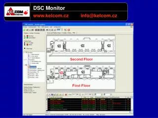
DSC Monitor [HOME] Main Screen Main Screen The screen is divided into several sections. The user can customize the look of the screen and choose which panels to be displayed. The information panels are located on the left.- Partitions are on the top, their status is displayed and can be changed.- In the middle, the zones, their status and partition assignment is displayed - The detailed info on the chosen partition or zone is located on the bottom Window in the middle of the screen shows- Site map with all detecting devices- Easy to understand zone status- System troubles list The bottom part contains the event log
DSC Monitor Main Screen Main Window Partitions Name and Status Menu Buttons One-Click Function Buttons List of Partitions Zones and Maps Detailed Information Event Buffer Filter Event Buffer
DSC Monitor [HOME] System and partitions status Panel System and partitions status Panel All partitions in the system are displayed in this panel. User can simply read the status of all partitions – the color of the round symbol before the partition name represents its status (Ready, Not ready, Armed, Disarmed, Alarm) Each partition can be Armed or Disarmed using buttons and
DSC Monitor System and partitions status Panel This symbol shows the partition status – Ready, Not ready,Armed, Disarmed, Alarm This symbol is function button used to arm or disarm partition Function button used to change the main window
DSC Monitor [HOME] Control panel Control panel This panel shows names of partitions, zones and site maps. Each name is preceded with the icon that represents it status.
DSC Monitor Control panel B – Name of the partition Z – Zones assigned to the partition List of maps
DSC Monitor [HOME] Information panel Information panel This panel shows the detailed information on the selected partitions and zones.
DSC Monitor Information panel Partitions information Zones information
DSC Monitor [HOME] Main Window Main Window • One of the following panels can be displayed in this window • Partition and zone description panel • Troubles panel • Site map panel
DSC Monitor [HOME] Partition and zone description panel Partition and zone description panel All zones and partitions are displayed in this panel. Each zone and partiion has its own name and a colour symbol representing its status. The screen can show 32, 64 or 128 zones.
DSC Monitor Partition and zone description panel Colour means specific partition status Colour means specific zone status;
DSC Monitor [HOME] Troubles panel Troubles panel All system troubles are shown in this panel.
DSC Monitor Troubles panel
DSC Monitor [HOME] Site map panel Site map panel All site maps are displayed in this panel. The software allows multiple site maps, this panel shows chosen one of them. Maps can be interconnected and allow simple movement from one to another. This results to better lucidity and easy to use. Such connection allows user to find alarm, particular zone, trouble and all information even in very complicated systems.
DSC Monitor Site map panel
DSC Monitor [HOME] Event log Event log This panel displays the list of events generated by the control panel and by the software
DSC Monitor Event log
DSC Monitor [HOME] Users Users • The software can be operated by different level of users • Standard operators, (their rights can be set), allowed to use the software • Logged on user • User not logged on • Users allowed to change the software configuration • Master user • Administrator
DSC Monitor [HOME] Specification Specification • On-line security system monitoring software • PC 4020 v3.3 and higher with PC 4401 module (On-line zone monitoring in disarmed mode only with PC 4020 v3.5 and higher) • PC 585 - PC 5020 and PC 1616 - PC 1864 with PC 5401 • Modules PC4401 and PC5401 are connected directly to computer COM port, a RS-232 to TCP/IP converter can be usedPC 4401 is connected to PC with PC-Link cable • Software is protected by HW keyLimitations of DEMO version - max. 2 partitions and 8 zones - communication terminated after 1 hour - project can not be saved and printed