Download
1 / 36
360 likes | 518 Views
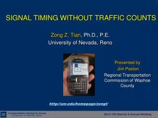
Topic 3 Basic Signal Timing and Coordination Principles. Signal System Classification. Traditional Systems Closed-Loop (Field Master) Centralized Computer Control Adaptive. Signal Timing Process. Data Collection. Field Implementation. Signal Timing Development. Basic Terminology.

E N D
Topic 3 Basic Signal Timing and Coordination Principles
Signal System Classification • Traditional Systems • Closed-Loop (Field Master) • Centralized Computer Control • Adaptive
Signal Timing Process Data Collection Field Implementation Signal Timing Development
Basic Terminology • Cycle • Phase Split • Phasing Sequence • Offset • Force-off
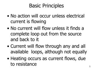
Cycle Length and Split • Cycle Length All signals must have a common cycle length to achieve coordination • Split Split = Green + Yellow + All-red
Signal Coordination Intersection #1 Intersection #2 East Bound
Offset • Offset is the time difference between two reference points • Offset must be specified by • Phase • Begin/end phase • Offset = 0 ~ cycle length
Offset Local zero Local zero ф 2,5 ф 1,5 ф 1,5 ф 2,6 ф 4,8 ф 2,6 ф 4,8 ф 3,7 When the local zero occurs at 40 sec of the master clock We say the Offset = 40 sec
Time-Space Diagram One-way Street Y=5 G=25 R=30 #1 2 8 2 8 4 4 6 6 EB Band G=35 Y=5 R=20 #2 2 2 8 4 8 4 6 6 Time
Time-Space DiagramTwo-way Street #1 Y=5 G=25 R=30 2 8 2 8 4 4 6 6 EB Band WB Band G=35 Y=5 R=20 2 2 #2 8 4 8 4 6 6 Time
Questions Question 1: 2 and 6 at intersection #1 turn to green at 60 sec, 2 and 6 at intersection #2 turn to green at 20 sec, what are the offset s at the two intersections, assuming the offset is referenced to the start of green of 2 and 6? Question 2: Given the offsets number in Q1, what will the offsets be if the offsets are referenced to the end of green of 2 and 6? Question 3: If the travel speeds are different for the two directions, will it affect the above offset results?
Offset and Transition • Synch point/clock: the time all offsets are referenced to. It is also called Master Clock Zero. It is usually set at 12:00 – 3:00 a.m. when traffic is light. 12:00 a.m. (Master Zero) Master Zero Master Zero Master Zero Local Zero Local Zero Local Zero Offset
Example • If the Synch point is set at 3:00 a.m., for a signal operating at an 90-sec cycle and an offset of 40, what would be the master clock timer and the local clock timer at 11:20 a.m.?
Transition Methods • Transition occurrences • Plan change • Preemption • Pedestrian • Transition methods/algorithms • Dwell • Max Dwell • Add • Subtract • Shortway
Offset and Transition 1 1 2 2 #1 8 4 6 5 6 5 WB: 8 sec EB: 20 sec #2 2 8 4 8 4 6
Bandwidth(Dual LT Leading) 1 1 2 2 #1 8 4 6 5 6 5 WB: 8 sec EB: 20 sec #2 2 8 4 8 4 6
Bandwidth - Adjusted(Dual LT Leading) 1 1 2 2 #1 8 4 6 5 6 5 WB: 12 sec EB: 20 sec #2 2 8 4 8 4 6
Bandwidth - Initial(Lead/Lag) 1 1 2 2 #1 8 4 6 5 6 5 WB: 12 sec EB: 20 sec #2 2 8 4 8 4 6
Bandwidth - Adjusted(Lead/Lag) 1 1 2 2 #1 8 4 6 5 6 5 WB: 20 sec EB: 20 sec #2 2 8 4 8 4 6
MOEs • Bandwidth Concept (PASSER II) • Bandwidth, seconds • Bandwidth Efficiency = Bandwidth/Cycle • Attainability = Bandwidth/gmin • System-Wide Delay (Synchro) • System-wide Stops and Delay (TRANSYT-7F)
Yellow Trap “Yellow trap” is a situation faced by a left-turn movement when the display of “yellow” occurs to both the left-turn phase and the adjacent through phase, but the opposing through is not terminating. (1) (3) (2) (5) (4)
Through movements move both directions. Left-turn yield to opposing through.
Yellow trap occurs when the leading left-turn sees yellow and thinks the opposing through phase will also end
Dallas phasing does not display yellow, and left-turn sees green ball and is supposed to still yield.
When left-turn sees yellow, the opposing phase also about to end
Yellow Trap • Only the leading left-turn has the “yellow trap” with protected/permitted phasing • Dallas Phasing solves the "yellow-trap" problem by holding a solid green indication. • Louvers are used to shield the left-turn display so that the green display in the left-turn signal cannot be easily seen by thru drivers. • When can a “yellow trap” occur with standard PPLT with left-turns leading or lagging? http://projects.kittelson.com/pplt/LearnAbout/Learn3.htm http://projects.kittelson.com/pplt/displays/dallas_doghouse_lag.htm
Summary • What is “Yellow Trap” and when it occurs? • What is the main purpose of using “Lead-Lag” phasing? Can “Lead-Lag” phasing increase an intersection capacity? • What is the exception that a different cycle length can be used at an intersection while still maintaining coordination? • Offset • Bandwidth • Time-Space Diagram
Lab Exercise • Use the Kietzke system (3 signals) to perform the following exercise. • Use the Synchro offset optimization (keep cycle length and splits unchanged) and answer the following questions: • What are the phasing sequences at each intersection? • How are the offsets referenced and what are the offsets? • Examine the timing solution and indicate where stops may occur if driving on the main street both directions. • Can you further improve the bandwidth by changing the phasing sequences from Synchro? Answer the same questions above. • Which intersection is controlling the bandwidth?
Lab Exercise • Use the Boulder Highway system (3 signals) to perform the following exercise. • Understand the existing timing sheets and compare with Synchro coding. • Use the Synchro offset optimization (keep cycle length and splits unchanged) and compare Synchro timing solution with the existing (bandwidth) • How was the phasing sequence changed at each signal? Can you further improve the bandwidth by changing the phasing sequences from Synchro? • Which intersection is controlling the bandwidth? • Try only with two intersections (Harmon and Tropicana) and see how the solution changes.
Signal Timing Sheets (NextPhase) Boulder Hwy/Tropicana Intersection • 1.1 – Schedule of timing plans • 2.3.x – Information of a timing plan: cycle, split, offset, sequence • 2.4.x – Phasing sequence • 2.5.x – Phase data (min green, yellow, all-red etc.) • 4.2.1- Phase designation (direction/movement) and ring structure
Lead/Lag Phasing WB = 36 sec EB = 16 sec
EB = 16 sec WB = 45 sec