Download
1 / 37
420 likes | 724 Views
Technological Design Basic Dimensioning with AutoCAD. How to annotate simple drawings for use in constructing an object. Learning Objectives. Be able to understand the basic rules of dimensioning Apply dimensions to objects in accordance with engineering standards

E N D
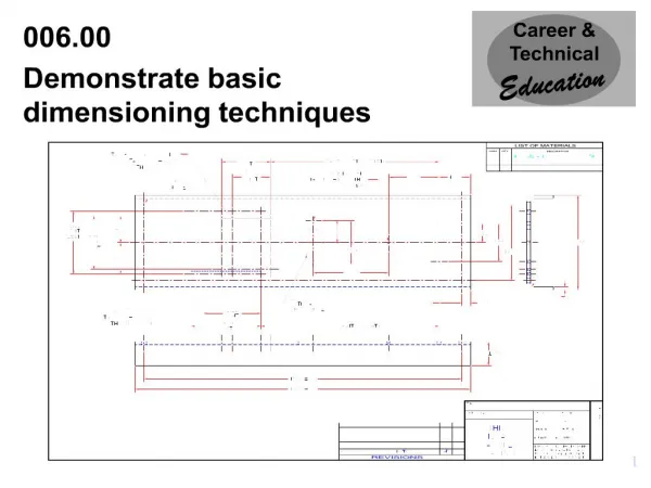
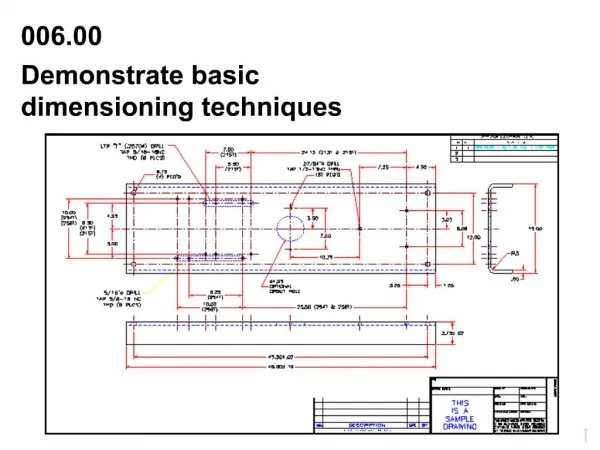
Technological DesignBasic Dimensioning with AutoCAD How to annotate simple drawings for use in constructing an object
Learning Objectives • Be able to understand the basic rules of dimensioning • Apply dimensions to objects in accordance with engineering standards • Define the following items: Dimension line, Extension line, Reference dimension, and Leader • Be able to recognize the following machined holes: Spotfaced, Counterbored, Countersunk, & Counterdrilled.
Types of Dimensions • Overall Dimensions • Overall : Length, Width, Height • Detail Dimensions • All other dimensions used to describe an object
Extension lines Extension lines should be offset from the part by one half the text height and should extend one text height beyond the dimension line
Dimension Spacing The first row of dimensions must be a minimum of 3 text heights away from the part.Any dimensions beyond it must be a minimum of 2 text heights apart
Avoid placing any dimensions on the part (inside the view) unless there is no other option. Avoid dimensioning to hidden features Always place the dimension where the characteristic shape is shown in the most descriptive view. (This means don’t place a dimension on object lines making a “T joint”.) Always dimension holes in their circular view by stating the diameter of drilled holes. Specify the hole depth of special features such as countersinking with a note following the dimension. Dimension rounded corners and arc features as radii where they appear in their rounded views. If the same value is repeated many times, then use a general note for the features. Dimension cylindrical objects as diameters in their rectangular view. Always place the first row of dimensions a minimum distance of 3 text heights away from the edge of the part. Additional stacks can be a minimum of 2 text heights away from each other. Keep dimensions between the views whenever possible Extension lines may cross each other and over other lines on the part, but dimension lines should never be crossed. The overall dimension should always be given. It should be placed outside of smaller dimensions and be the furtherest dimension from the part. Dimensioning Rules See Essentials of Engineering Design Graphics Chapter 4
Do not duplicate dimensions and avoid using unnecessary or superfluous dimensions When all of the dimensions are expressed in inches, do not use inch mark (“) or the abbreviation for inches (in.) For drawings dimensioned in inches, values less that one inch should not be preceded with a zero. For metric drawings, omit the use of the millimeter (mm) notation following the numeral, as millimeters are the default units. The origin for baseline or ordinate dimensions used as a datum should be extended from a finished edge of the part. Conserve space and time by using abbreviations and standardized symbols whenever possible. Reference dimensions should be placed in parentheses or should include the abbreviation “REF”. Basic sizes (to be toleranced) should be placed inside a rectangular box Extend leaders from the first of last word in a note. Point them toward the center of circular features that they are specifying. Place dimensions among the various views to avoid crowding. Stagger horizontal dimensions to avoid contact or crowding of values. Dimensioning Rules See Essentials of Engineering Design Graphics Chapter 4
1. Avoid placing dimensions on the part (inside of the view). See Essentials of Engineering Design Graphics Chapter 4
2. Avoid dimensioning to hidden features There is one exception:……When the hidden line is a finished (√) surface See Essentials of Engineering Design Graphics Chapter 4
3. Always place dimensions where the characteristic shape is shown in the most descriptive view See Essentials of Engineering Design Graphics Chapter 4
4. Always dimension holes in their circular view with the Ø. Specify special features (hole types) with a note. Also: Remember to locate hole position with ordinate dimensions to hole centers See Essentials of Engineering Design Graphics Chapter 4
5. Dimension rounded corners and arc features as radii where they appear in their rounded view. See Essentials of Engineering Design Graphics Chapter 4
6. If the same value is repeated many times, then use a general note for the feature. (ALL FILLETS AND ROUNDS ARE .125R) See Essentials of Engineering Design Graphics Chapter 4
7. Dimension cylinders in their rectangular view with a diameter symbol….Ø. See Essentials of Engineering Design Graphics Chapter 4
8. Place the first row of dimensions 3 text heights (3/8 ”or 10 mm) away from the edge of the part. Additional stacks of dimensions can be a minimum of two text heights (1/4 ”or 6 mm) away from each other See Essentials of Engineering Design Graphics Chapter 4
9. Keep dimensions between views whenever possible . See Essentials of Engineering Design Graphics Chapter 4
10. Extension lines may cross each other and over other lines on the part, but dimension lines should never be crossed. (Hint no “arrow-headed” lines can cross “arrow-headed” lines) See Essentials of Engineering Design Graphics Chapter 4
11. The overall dimension should always be given. It should be placed outside of smaller dimensions and be the farthest from the part. See Essentials of Engineering Design Graphics Chapter 4
12. Do not duplicate dimensions and avoid using unnecessary or superfluous dimensions See Essentials of Engineering Design Graphics Chapter 4
13. When all of the dimensions are expressed as inches. DO NOT use inch marks ('') or the abbreviation (.in) See Essentials of Engineering Design Graphics Chapter 4
14. For drawings dimensioned in inches, values less than 1 inch should not be proceeded with a zero. See Essentials of Engineering Design Graphics Chapter 4
15. For metric dimensions less than 1 mm DO place a zero in front of the decimal point. See Essentials of Engineering Design Graphics Chapter 4
16. For metric drawings, omit the use of the millimeter (mm) notation following the numeral, as millimeters are the default units. See Essentials of Engineering Design Graphics Chapter 4
17. The origin for baseline or ordinate dimensions used as a datum should be extended from a finished edge of the part. See Essentials of Engineering Design Graphics Chapter 4
18. Conserve space and time by using abbreviations and standardized symbols whenever possible. See Essentials of Engineering Design Graphics Chapter 4
19. Reference dimensions should be placed in parenthesis or should include the abbreviation “REF”. Basic sizes (to be toleranced) should be placed inside of a rectangular box See Essentials of Engineering Design Graphics Chapter 4
20. Extend leaders from the first or last word in a note. Point them toward (but not touch) the center of the circular features that they are specifying. See Essentials of Engineering Design Graphics Chapter 4
21. Place dimensions among the various views to avoid crowding. Stagger horizontal dimensions to avoid contact or crowding of the values See Essentials of Engineering Design Graphics Chapter 4
Angular features:Dimension angular features with either: X,Y coordinate location or Vertex location & degrees See Essentials of Engineering Design Graphics Chapter 4
Dimension Styles Aligned dimensions align with individual dimension lines. Unidirectional dimensions are read from the lower left corner of the sheet See Essentials of Engineering Design Graphics Chapter 4
A short review on Dimension “elements” • What is… • an Extension line ? • an Extension line gap ? • an Extension line extension ? • a Dimension line ? • a Dimension numeral ? • a leader ? • When are… • Decimals used ? Not used ? • Unit designators (in. or mm) listed on dimension lines ? • What size… • Is an Arrowhead ?
Dimensioning Errors: • What is wrong with:
Dimensioning Errors: • What is wrong with:
Dimensioning Errors: • What is wrong with:
Dimensioning Errors: • What is wrong with: