Download
1 / 65
650 likes | 924 Views
MPLS CoS Clarence Filsfils cfilsfil@cisco.com. DiffServ Architecture. Presentation_ID. 2. © 1999, Cisco Systems, Inc. . DiffServ Architecture RFC 2475.

E N D
DiffServ Architecture Presentation_ID 2 © 1999, Cisco Systems, Inc.
DiffServ ArchitectureRFC 2475 “This architecture achieves scalability by implementing complex classification and conditioning functions only at network boundary nodes, and by applying per-hop behaviors to aggregates of traffic which have been appropriately marked using the DS field in the IPv4 or IPv6 headers [DSFIELD]. Per-application flow or per-customer forwarding state need not be maintained within the core of the network.” RFC2475 Architecture for Differentiated Services
DiffServ Architecture SLS/TCS 0. Negociation and agreement of an SLS/TCS
DiffServ Architecture 1. Pre-marking in the source domain - per-application/host basis - per-default-gateway basis
DiffServ Architecture SLS/TCS 2. Egress- boundary DS node of source domain applies traffic conditioning to ensure SLS/TCS compliance, hence causing possible re-marking, dropping and shaping
DiffServ Architecture SLS/TCS 3. Classification according to SLS 4. Conditioning according to TCS 5. Assignment to a BA (DSCP setting)
DiffServ Architecture 6. Forwarding according to PHB mapped to set DSCP
DiffServ Architecture SLS’/TCS’ If downstream DS domain support same service provisioning policy, same PHBs and DSCP/PHB mappings Then 7: No-op Else 7’a: SLS’/TCS’ negotiation 7’b: Conditioning according to TCS’
DS fieldRFC 2474 DS field DSCP CU • DS field replaces IPv4 ToS, IPv6 Traffic Class • DSCP = 6 bits : “xxxxxx” notation
EF PHB definitionRFC2598 • EF PHB ensures a minimum departure rate • DSCP: “101110” • EF PHB can be used to build a low loss, low latency, low jitter, assured bandwdith, e2e service through DS domains
AF PHB definitionRFC2597 AF Class 1: 001dd0 AF Class 2: 010dd0 • 4 independently forwarded AF classes • Within each AF class, 3 levels of drop prec01 < 10 < 11, with active Q mgt (RED) • 4 independent capacity management plans AF Class 3: 011dd0 AF Class 4: 100dd0 01: Low Drop 10: Medium Drop 11: High Drop
AF PHB definition (Cont) • Assured Forwarding (AF) PHB group is a means for a provider DS domain to offer different levels of forwarding assurances for IP packets received from a customer DS domain • Olympic Service (Gold, Silver, Bronze) • gold (C1) >= silver (C2) >= bronze (C3) • No quantifiable timing requirements! • delay or delay variation
AF PHB definition (Cont) • Forwarding assurance of an IP packet: • resources allocated to the AF class • local resource allocation config (buffer and link BW) • the current load of that AF class • conditioning at the DS domain edge • the drop precedence of the packet • conditioning at the DS domain edge
Cisco DiffServ Architecture ACLQPPB CARTSNetflow CEF CBWFQFBWFQWRED TS DiffServ Architecture Functional Blocks Classifier Conditioner Forwarding PHB Conditioner MeteringDroppingMarkingAccounting SchedulingDropping Shaping
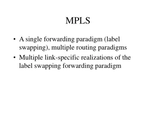
MPLS/DiffServ: the obvious fit!Scalability! 1000’s of flows Different BA’s of the same FEC follow the same LSP MPLS: FEC toLabel Imposition MPLS: Label Switching DS: PHB based on DSCP DS: Behavior Aggregate’s DSCP Imposition
MPLS/DiffServ: the obvious fit!Enhanced Services 1000’s of flows Per-DSCP FEC would allow for new services (eg. per-CoS TE) MPLS/DiffServ: per-cos per-FEC Label Imposition with DHCP imposition MPLS: Label Switching DS: PHB based on DHCP
VPI/VCI crosstable MPLS/DiffServ: the obvious fit!Enhanced Services PNNI Routing IP Routing ATM Forum Stack MPLS Stack LDP Signalling UNI/NNI Signal. • ATM switch runs IP Routing Protocol and IP QoS functions • “Ship in the Night” Model • More scalability. IP DiffServ intelligence. IP QoS ATMF QoS
MPLS DiffServ Presentation_ID 19 © 1999, Cisco Systems, Inc.
Coloring MPLS Frames • Two methods are possible • Using the EXP bits in the MPLS header and mapping DSCP to EXP • convenient for Frame-based Interface • Mapping a label per-CoS per-FEC • convenient for ATM-based interface
0 1 2 3 0 1 2 3 4 5 6 7 8 9 0 1 2 3 4 5 6 7 8 9 0 1 2 3 4 5 6 7 8 9 0 1 +-+-+-+-+-+-+-+-+-+-+-+-+-+-+-+-+-+-+-+-+-+-+-+-+-+-+-+-+-+-+-+-+ | Label | EXP |S| TTL | +-+-+-+-+-+-+-+-+-+-+-+-+-+-+-+-+-+-+-+-+-+-+-+-+-+-+-+-+-+-+-+-+ Using the EXP bits • Copy of Precedence into EXP • Mapping of DSCP into EXP MPLS Domain Non-MPLS Domain IPv4 Packet MPLS Hdr Prec: xyz MPLS EXP: xyz Prec: xyz
0 1 2 3 0 1 2 3 4 5 6 7 8 9 0 1 2 3 4 5 6 7 8 9 0 1 2 3 4 5 6 7 8 9 0 1 +-+-+-+-+-+-+-+-+-+-+-+-+-+-+-+-+-+-+-+-+-+-+-+-+-+-+-+-+-+-+-+-+ | Label | EXP |S| TTL | +-+-+-+-+-+-+-+-+-+-+-+-+-+-+-+-+-+-+-+-+-+-+-+-+-+-+-+-+-+-+-+-+ Label-inferred CoSdraft-ietf-mpls-diff-ext-01.txt • DSCP to Label mapping Dest-CoS Label P/p CoS1 17 IPv4 Packet P/p CoS2 22 P/p CoS3 25 Prec: xyz P/p CoS4 12
Enforcing PHB’s on non-ATM interfaces Presentation_ID 23 © 1999, Cisco Systems, Inc.
Frame MPLS CoSStraightforward • Same Mechanisms as IP CoS • Link Sharer: IOS CBWFQ • Active Q mgnt and differentiated drop: IOS WRED • AF and EF PHB’s • Class lookup from either • MPLS CoS/EXP • MPLS Label inferred CoS • Undistinguishable from IPv4 DiffServ
Enforcing PHB’s on ATM interfaces Presentation_ID 25 © 1999, Cisco Systems, Inc.
PNNI Routing IP Routing LDP Signalling UNI/NNI Signal. VPI/VCI crosstable IP QoS ATMF QoS ATM MPLS CoSGreat Opportunity! • Peer Model! • IP intelligence at every hop • IP-friendly mech. on ATM switches! • Diffserv instead of per-VC ATM QoS • Superior Resource Utilisation • Simpler Resource Allocation
Two Modes • Multi-LSP in TBR mode • Single LSP in ABR mode • Each has advantage and drawbacks TBR: Tag Bit Rate: ATM service category designed for Differv/MPLS
Multi-VC TBR modeControl Plane ATM LSR • TDP signals up to 4 parallel LSPs for the same prefix • CoS <--> LSPs mapping at the edge LSR • Optional setting of CLP (based on DHCP) Parallel TBR LSPs
Multi-VC TBR modeData Path ATM LSR Parallel TBR LSPs • Edge LSR: • per CoS WFQ + per CoS WRED • ATM-LSR • per CoS WFQ + per CoS WEPD • NO per-LVC management!!! • Scalability and better muxing
Multi-VC TBR modeExample Per COS WFQ • Queuing on all links is per-class WFQ (not per LSP) • Resource allocation • Assign weight to each class on per-link basis (e.g. Premium gets 80% of link, Standard gets 20%) • Choice of weights based on expected load & desired performance PER CLASS • No per-router-pair configuration (config independent of topology & geography)
ABR LSP ATM LSR Single `VC’ ABR mode • 1 single LVC per FEC • ABR control algorithms are enabled on LSPs • Extention of “IPATMCoS” feature • ATM-LSRs push congestion towards edge LSRs • Edge-LSRs: WRED/WFQ per-LSP queues
Single VC ABR mode • ATM-LSR Scheduling = per-VC ABR • ABR parameters: • MCR is effectively zero (to avoid loss/blocking) • “Relative bandwidth” parameter carried by TDP and used by ABR algorithm
Single VC ABRExample KleinStadt B Paris London A Per VC ABR Tarifa • Equal sharing of link A-B is not always desirable: • Configure relative bandwidth on router-pair basis,e.g. Tarifa-KleinStadt = 1; London-Paris = 100 • Resource Allocation : • Sharing of Bandwidth across Edge Pairs via “Relative BW” on a per LSP basis • Sharing of Bandwidth across COS performed through WRED/CBWFQ on Edge
Single-ABR vs Multi-TBR • Multi-VC TBR Mode: • Congestion managed directly at every hop (IP and ATM hops) • Possible Discard at every hop • Resource Allocation per COS per link; does not have to concern itself with topology and geography • Single-VC ABR: • No Loss in the ATM fabric • Discard/Scheduling possible only on the Edge performed by Routers • Resource Allocation optionally per Pair of Edge Routers.
MPLS over ATMF PVCA special Case ATM Forum ATM ATM Forum PVC • Generic Frame MPLS CoS Case! • A Frame LSR uses ATM-F PVC with chosen ATM QoS • Service Differentiation on Frame LSRs at edge of ATM • Use IPATMCoS features! LDP
MPLS over IPATMCoSper-VC IP QoS • Congestion pushed back at the edge • per-VC ATM-F shaping • CBWFQ/WRED on IP per-VC Queue ATM-F service class enforced
MPLS over IPATMCoSBundle IP QoS • per-VC ATM-F shaping • DSCP to VC mapping • WRED on IP per-VC Q ATM-F service class enforced 1! IGP adajacency
MPLS VPN CoS Presentation_ID 38 © 1999, Cisco Systems, Inc.
MPLS VPN QoS Architecture • 2 very distinct point of views: • How the SP will market the service (SLA) • What are the mechanisms for SP to meet the commitments/SLA • FR analogy: • sell 64 kb/s CIR for 99.5% of the time • reserve 64/overbooking kb/s + admission control + selective discard + …
ECR 512k ICR 512k ECR 128k ECR 128k ICR 256k ICR 256k How to market MPLS VPN CoS?ICR concept - hose model VPN_A site 4 VPN SP VPN_A site 2 VPN_A site 3 Hose Model (point-to-multipoint commodity)Draft-duffield-vpn-qos-framework.txt, AT&T
Proposed SLA for CoS C1 • As long as for each site S of VPN X: • S sends less than ICR • S receives less than ECR (optional: double-ended SLA) • Then: • loss property is 10^(-n1) • RTT is < m1 ms
Extensible to multiple CoS! CoS X: [nx, mx], price Px Gold: [-10, 100ms], $$$ Silver: [-8, 200ms], $$ BE: [be, be], $
How it should not be marketed • Should not be marketed as Frame Relay QoS: • N1 kb/s guaranteed from Site 1 to Site 2 • N2 kb/s guaranteed from Site 1 to Site 3 • N3 kb/s guaranteed from Site 2 to Site 3 • … • Layer 2 based VPNs (ie FR or ATM) address that need
Advantage of this SLA model • Any to any connectivity • Without requiring the customer to have a precise and complete knowledge of its traffic matrix • Matrix of ICR/ECR allows the provider to better engineer his network (hence, to lower the cost of the commodity) • Per-usage billing is still possible (ICR/ECR then only serve as boundaries)
How to meet SLA • Enforcement of ICR: • CAR: policing in/out of profile • Enforcement of ECR • CAR/TS • MPLS CoS in the SP’s backbone • single-ABR, multi-TBR mode • DiffServ engineering
DiffServ Engineering • Scalability: no per-VPN QoS in BB!!! • This is a pure diffserv design! • Per-Class Scheduling/Discarding at every hop • Resource Allocation based on ICR/ECR sold • share each trunk between different Classes • start conservative • then monitor traffic per class and fine tune • Optimise with per-class Traffic Engineering • Cisco Service Management tool for Tag VPN QoS provisioning
DiffServ EngineeringCapacity Management Presentation_ID 47 © 1999, Cisco Systems, Inc.
DiffServ ArchitectureThe Service Offer 1. The routing topology 2. The speed of the links 3. The link sharing ratios (CBWFQ %) THE Service Offer
DiffServ ArchitectureThe Service Demand 1. The matrix of ICR 2. The matrix of ECR THE Service Demand
DiffServ ArchitectureThere is no magic • Service Offer (per class) >= Service Demand (per class) • How to achieve this? • ‘provisioned QoS’