Download
1 / 19
210 likes | 228 Views
MODEL REFERENCE ADAPTIVE CONTROL OF PERMANENT MAGNET SYNCHRONOUS MOTOR DRIVE WITH FORCED DYNAMICS. Model of Permanent Magnet Synchronous Motor.

E N D
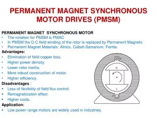
MODEL REFERENCE ADAPTIVE CONTROL OF PERMANENT MAGNET SYNCHRONOUS MOTOR DRIVE WITH FORCED DYNAMICS
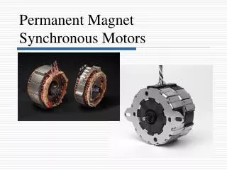
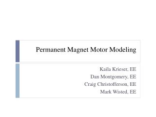
Model of Permanent Magnet Synchronous Motor Non-linear differential equations formulated in the magnetic field-fixed d,q co-ordinate system describe the permanent magnet synchronous motor and form the basis of the control system development.
Motor equation for id=0 1. Vector control condition Demanded dynamic MCL produces demanded values of the current components 2. Linearising function • Master & Slave Control Laws B. Slave control law
The pseudo-sliding mode observer These terms are treated together as a disturbance vector The remainder of the motor equation forms the basis of the real time model of the observer.
The basic stator current vector pseudo sliding-mode observer is given by: The required estimates are equivalent values where is a high gain For the purpose of producing a useful formula for perfect constant parameter estimates may be assumed: unfiltered angular velocity estimate can be extracted: The Sliding Mode Observer and Angular Velocity Extractor
where design of: needs adjustment of the one parameter only or as two different poles: The Filtering Observer Filtered values of and are produced by theobserverbased on Kalman filter Load torque is modelled as a state variable Electrical torque of SM is treated as an external input to the model
Original control structure of speed controlled synchronous motor ua Slave control law POWER electronics ia_dem id_dem Master control law Transf. dq /α,β and α,β/a,b,c ib_dem ub iq_dem SMPM ic_dem uc ia ib ua,b,c Transf. abc / a,b and a,b/d,q ia ib ic Discrete two phase oscillator cosq sinq id iq uq iq ud id id vd_ekv Sliding mode Observer Angular velocity Extractor iq Filtering observer vq_ekv
Inner & Middle Loop (real system) correction loop Model TF Reference model (of closed-loop system) Parameter mismatch increases a correction Mason’s rule MRAC outer loop
Experimental Verification Parameters of the PMSM: Pn=475 W; wn=157 rad/s; Tn=0,47 Nm Equivalent Circuit Parameters: Rs=1,26 W; Ld=9,34 mH; Lq=9,2 mH; p=2; J=0,0005 kg.m2; YPM=0,112 Vs Parameters of IGBT Semikron6MBI-060 are as follows: nominal voltage: 1000 [V] , nominal current: 6x10 [A]. Current sensors are as follows: LEM LTA 50P/SPI.
Rotor Speed without MRAC without MRAC EXPERIMENTAL RESULTS 1
Rotor Speed including MRAC EXPERIMENTAL RESULTS 2
a) b) d) c) Simulation resultswithout outer loop and with outer loop b) a) c) d) a) stator currents, b) rotor mg. fluxes, c) applied torque and estimated torque and rotor speed from filtering observer d) rotor speed and ideal speed from transfer function
Experimental Resultswithout outer loop and with outer loop a) a) b) b) a) ideal speed and estimated speed from filtering observer and b) ideal speed with real rotor speed from speed sensor.
Constant Acceleration First Order Dynamic Second Order Dynamic Acceleration Demands for Three Various Dynamics
Constant Acceleration Second Order Dynamic wd= 600 rpm, Tramp= 0.05 s wd= 600 rpm, Tsettl= 0.3 s First Order Dynamic wd= 800 rpm, Tsettl= 0.3 s Experimental Results for Synchronous Motor Drive
60 z=0.5 50 40 z=2 30 20 z=1 10 0 -10 -0.2 0 0.2 0.4 0.6 0.8 Second Order Dynamics for Various Damping Factor Tsettl=0.15 s , wd = 40 rad/s
Conclusions: • A new approach to the control of electric drives with permanent magnet synchronous motors, when original forced dynamics control system was completed with outer control loop based on MRAC, has been developed and experimentally proven. • Three various prescribed dynamics to speed demands were achieved and beneficial influence of added control loops was observed. • Application to the vector controlled drive with PMSM is possible. Further improvement of this control technique can continue via application of more sophisticated PWM strategy.