Download
1 / 26
270 likes | 404 Views
Force Vectors Phy621- Gillis. Contents. Introduction Resultant of Two Forces Vectors Addition of Vectors Resultant of Several Concurrent Forces Sample Problem 2.1 Sample Problem 2.2 Rectangular Components of a Force: Unit Vectors Addition of Forces by Summing Components.

E N D
Force Vectors Phy621- Gillis
Contents Introduction Resultant of Two Forces Vectors Addition of Vectors Resultant of Several Concurrent Forces Sample Problem 2.1 Sample Problem 2.2 Rectangular Components of a Force: Unit Vectors Addition of Forces by Summing Components Sample Problem 2.3 Equilibrium of a Particle Free-Body Diagrams Sample Problem 2.4 Sample Problem 2.6 Rectangular Components in Space Sample Problem 2.7
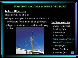
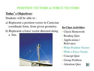
Introduction • The objective is to investigate the effects of forces: - replacing multiple forces acting on a particle with a single equivalent or resultant force, - relations between forces acting on a particle that is in a state of equilibrium.
force: action of one body on another; characterized by its point of application, magnitude, line of action, and sense. • Experimental evidence shows that the combined effect of two forces may be represented by a single resultant force. Resultant of Two Forces • The resultant is equivalent to the diagonal of a parallelogram which contains the two forces in adjacent legs. • Force is a vector quantity.
Vector: parameters possessing magnitude and direction which add according to the parallelogram law. Examples: displacements, velocities, accelerations. • Equal vectors have the same magnitude and direction. • Negative vector of a given vector has the same magnitude and the opposite direction. Vectors • Scalar: parameters possessing magnitude but not direction. Examples: mass, volume, temperature
Trapezoid rule for vector addition • Triangle rule for vector addition • Law of cosines, C B C • Law of sines, B • Vector addition is commutative, • Vector subtraction Addition of Vectors
Addition of three or more vectors through repeated application of the triangle rule • The polygon rule for the addition of three or more vectors. • Vector addition is associative, • Multiplication of a vector by a scalar Addition of Vectors
Concurrent forces: set of forces which all pass through the same point. A set of concurrent forces applied to a particle may be replaced by a single resultant force which is the vector sum of the applied forces. • Vector force components: two or more force vectors which, together, have the same effect as a single force vector. Resultant of Several Concurrent Forces
Sample Problem 2.1 • SOLUTION: • Graphical solution - construct a parallelogram with sides in the same direction as P and Q and lengths in proportion. Graphically evaluate the resultant which is equivalent in direction and proportional in magnitude to the the diagonal. The two forces act on a bolt at A. Determine their resultant. • Trigonometric solution - use the triangle rule for vector addition in conjunction with the law of cosines and law of sines to find the resultant.
Graphical solution - A parallelogram with sides equal to P and Q is drawn to scale. The magnitude and direction of the resultant or of the diagonal to the parallelogram are measured, • Graphical solution - A triangle is drawn with P and Q head-to-tail and to scale. The magnitude and direction of the resultant or of the third side of the triangle are measured, Sample Problem 2.1
Sample Problem 2.1 • Trigonometric solution - Apply the triangle rule.From the Law of Cosines, From the Law of Sines,
Sample Problem 2.2 • SOLUTION: • Find a graphical solution by applying the Parallelogram Rule for vector addition. The parallelogram has sides in the directions of the two ropes and a diagonal in the direction of the barge axis and length proportional to 5000 lbf. A barge is pulled by two tugboats. If the resultant of the forces exerted by the tugboats is 5000 lbf directed along the axis of the barge, determine • Find a trigonometric solution by applying the Triangle Rule for vector addition. With the magnitude and direction of the resultant known and the directions of the other two sides parallel to the ropes given, apply the Law of Sines to find the rope tensions. • the tension in each of the ropes for a = 45o, • the value of a for which the tension in rope 2 is a minimum. • The angle for minimum tension in rope 2 is determined by applying the Triangle Rule and observing the effect of variations in a.
Graphical solution - Parallelogram Rule with known resultant direction and magnitude, known directions for sides. • Trigonometric solution - Triangle Rule with Law of Sines Sample Problem 2.2
The angle for minimum tension in rope 2 is determined by applying the Triangle Rule and observing the effect of variations in a. • The minimum tension in rope 2 occurs when T1 and T2 are perpendicular. Sample Problem 2.2
May resolve a force vector into perpendicular components so that the resulting parallelogram is a rectangle. are referred to as rectangular vector components and • Define perpendicular unit vectors which are parallel to the x and y axes. • Vector components may be expressed as products of the unit vectors with the scalar magnitudes of the vector components.Fx and Fyare referred to as the scalar components of Rectangular Components of a Force: Unit Vectors
Wish to find the resultant of 3 or more concurrent forces, • Resolve each force into rectangular components • The scalar components of the resultant are equal to the sum of the corresponding scalar components of the given forces. • To find the resultant magnitude and direction, Addition of Forces by Summing Components
Sample Problem 2.3 • SOLUTION: • Resolve each force into rectangular components. • Determine the components of the resultant by adding the corresponding force components. • Calculate the magnitude and direction of the resultant. Four forces act on bolt A as shown. Determine the resultant of the force on the bolt.
SOLUTION: • Resolve each force into rectangular components. • Determine the components of the resultant by adding the corresponding force components. • Calculate the magnitude and direction. Sample Problem 2.3
Particle acted upon by three or more forces: • graphical solution yields a closed polygon • algebraic solution • Particle acted upon by two forces: • equal magnitude • same line of action • opposite sense Equilibrium of a Particle • When the resultant of all forces acting on a particle is zero, the particle is in equilibrium. • Newton’s First Law: If the resultant force on a particle is zero, the particle will remain at rest or will continue at constant speed in a straight line.
Free-Body Diagram: A sketch showing only the forces on the selected particle. Free-Body Diagrams Space Diagram: A sketch showing the physical conditions of the problem.
Sample Problem 2.4 • SOLUTION: • Construct a free-body diagram for the particle at the junction of the rope and cable. • Apply the conditions for equilibrium by creating a closed polygon from the forces applied to the particle. • Apply trigonometric relations to determine the unknown force magnitudes. In a ship-unloading operation, a 3500-lb automobile is supported by a cable. A rope is tied to the cable and pulled to center the automobile over its intended position. What is the tension in the rope?
Solve for the unknown force magnitudes. Sample Problem 2.4 • SOLUTION: • Construct a free-body diagram for the particle at A. • Apply the conditions for equilibrium.
Sample Problem 2.6 • SOLUTION: • Choosing the hull as the free body, draw a free-body diagram. • Express the condition for equilibrium for the hull by writing that the sum of all forces must be zero. It is desired to determine the drag force at a given speed on a prototype sailboat hull. A model is placed in a test channel and three cables are used to align its bow on the channel centerline. For a given speed, the tension is 40 lb in cable AB and 60 lb in cable AE. Determine the drag force exerted on the hull and the tension in cable AC. • Resolve the vector equilibrium equation into two component equations. Solve for the two unknown cable tensions.
SOLUTION: • Choosing the hull as the free body, draw a free-body diagram. • Express the condition for equilibrium for the hull by writing that the sum of all forces must be zero. Sample Problem 2.6
Sample Problem 2.6 • Resolve the vector equilibrium equation into two component equations. Solve for the two unknown cable tensions.
This equation is satisfied only if each component of the resultant is equal to zero Sample Problem 2.6