Download
1 / 77
1.1k likes | 2.07k Views
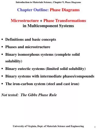
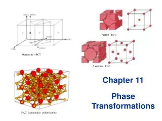
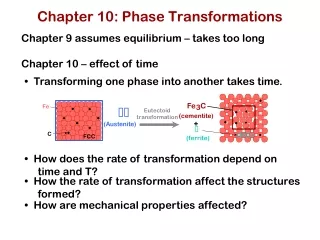
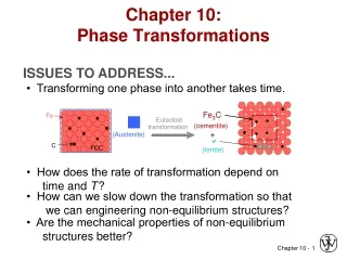
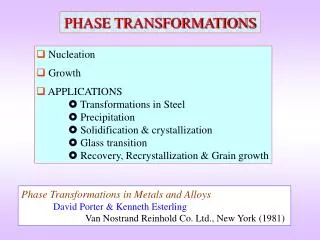
PHASE TRANSFORMATIONS. Nucleation Growth APPLICATIONS Transformations in Steel Precipitation Solidification & crystallization Glass transition Recovery, Recrystallization & Grain growth . Phase Transformations in Metals and Alloys David Porter & Kenneth Esterling

E N D
PHASE TRANSFORMATIONS • Nucleation • Growth • APPLICATIONS Transformations in Steel Precipitation Solidification & crystallization Glass transition Recovery, Recrystallization & Grain growth Phase Transformations in Metals and Alloys David Porter & Kenneth Esterling Van Nostrand Reinhold Co. Ltd., New York (1981)
Based on Mass transport PHASE TRANSFORMATIONS Diffusional Martensitic Based on order PHASE TRANSFORMATIONS 1nd ordernucleation & growth 2nd orderEntire volume transforms
Bulk Gibbs free energy ↓ Energies involved Interfacial energy ↑ Strain energy ↑ Solid-solid transformation New interface created Volume of transforming material • The concepts are illustrated using solidification of a metal
1nd ordernucleation & growth Growthtill is exhausted Nucleationof phase Trasformation → + =
Liquid→ Solidphase transformation • On cooling just below Tm solid becomes stable • But solidification does not start • E.g. liquid Ni can be undercooled 250 K below Tm ↑ t Solid stable Liquid stable G Solid (GS) G → ve G → Liquid (GL) T G → +ve “For sufficient Undercooling” Tm T → T - Undercooling
Solidification Nucleation Growth = + Nucleation Homogenous Nucleation • Liquid → solidwalls of container, inclusions • Solid → solid inclusions, grain boundaries, dislocations, stacking faults Heterogenous • The probability of nucleation occurring at point in the parent phase is same throughout the parent phase • In heterogeneous nucleation there are some preferred sites in the parent phase where nucleation can occur
Neglected in L → S transformations Homogenous nucleation r3 r2 1
By setting dG/dr = 0 the critical values (corresponding to the maximum) are obtained (denoted by superscript *) • Reduction in free energy is obtained only after r0 is obtained As Gv is ve, r*is +ve Trivial G → Embryos Supercritical nuclei r →
The bulk free energy reduction is a function of undercooling Turnbull approximation Tm Increasing T Decreasing G* Decreasing r* G → r →
No. of critical sized particles Frequency with which they become supercritical x Rate of nucleation = No. of particles/volume in L → lattice vibration frequency (~1013 /s) s* atoms of the liquid facing the nucleus Critical sized nucleus Jump taking particle to supercriticality→ nucleated (enthalpy of activation = Hd) Critical sized nucleus
G*↑ I ↓ • T ↑ I ↑ T = Tm→G* = → I = 0 Tm Increasing T T (K) → 0 T = 0 →I = 0 I →
Heterogeneous nucleation Consider the nucleation of from on a planar surface of inclusion Interfacial Energies Alens Created Acircle Created Acircle Lost Surface tension force balance Vlens = h2(3r-h)/3 Alens = 2rh h = (1-Cos)r rcircle = r Sin
G*hetero (0o) = 0no barrier to nucleation G*hetero (180o) = G*homono benefit G*hetero / G*homo→ G*hetero (90o) = G*homo/2 No wetting Complete wetting Partial wetting (degrees)→
= f(number of nucleation sites) ~ 1026 = f(number of nucleation sites) ~ 1042 BUTthe exponential term dominates Ihetero > Ihomo
Choice of heterogeneous nucleating agent • Small value of • Choosing a nucleating agent with a low value of (low energy interface) • (Actually the value of ( ) will determine the effectiveness of the heterogeneous nucleating agent → high or low ) • low value of → Crystal structure of and are similar and lattice parameters are as close as possible • Seeding rain-bearing clouds → AgI or NaCl → nucleation of ice crystals • Ni (FCC, a = 3.52 Å) is used a heterogeneous nucleating agent in the production of artificial diamonds (FCC, a = 3.57 Å) from graphite
Hd Hd – vatom Gv phase phase Growthtill is exhausted Nucleationof phase Trasformation → + = Growth • At transformation temperature the probability of jump of atom from → (across the interface) is same as the reverse jump • Growth proceeds below the transformation temperature, wherein the activation barrier for the reverse jump is higher
Tm Maximum of growth rate usuallyat higher temperature than maximum of nucleation rate U T Increasing T I T (K) → 0 I, U, T →
1.0 0.5 X→ 0 t →
A type of phase diagram Time – Temperature – Transformation (TTT) diagrams Small driving force for nucleation Tm Tm Replot T Time for transformation T (K) → T (K) → 0 0 T (rate sec1)→ t (sec)→ Growth sluggish
TTT diagram → phase transformation Increasing % transformation T (K) → 99% = finish 1% = start t (sec)→
Turnbull’s approximation Solid (GS) G G → T Liquid (GL) Tm T →
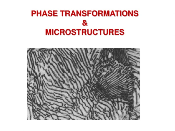
APPLICATIONS Phase Transformations in Steel Precipitation Solidification and crystallization Glass transition Recovery recrystallization & grain growth
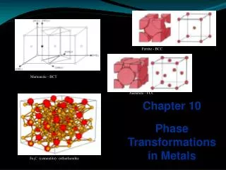
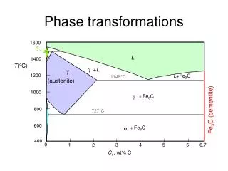
Fe-Cementite diagram EutecticL → + Fe3C Peritectic L + → L 1493ºC L + 1147ºC 0.1 %C 2.06 Eutectoid → + Fe3C + Fe3C 723ºC 0.025 %C + Fe3C T → Fe3C Fe 0.8 6.7 0.16 4.3 %C →
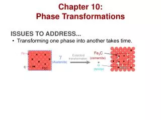
Time- Temperature-Transformation (TTT) Curves – Isothermal Transformation Eutectoid steel (0.8%C) 800 Eutectoid temperature 723 Austenite Coarse Pearlite 600 Fine 500 Pearlite + Bainite 400 T → Bainite 300 Austenite Ms 200 Not an isothermaltransformation Mf 100 Martensite 103 102 104 1 0.1 10 105 t (s) →
Time- Temperature-Transformation (TTT) Curves – Isothermal Transformation Eutectoid steel (0.8%C) 800 Eutectoid temperature 723 Austenite Pearlite 600 + Fe3C 500 Pearlite + Bainite 400 T → Bainite 300 Ms 200 Mf 100 Martensite 103 102 104 1 0.1 10 105 t (s) →
Continuous Cooling Transformation (CCT) Curves Eutectoid steel (0.8%C) 800 Eutectoid temperature 723 Austenite 600 Pearlite 500 Original TTT lines 400 T → 300 Ms 200 Cooling curvesConstant rate Mf 100 Martensite 103 102 104 1 0.1 10 105 t (s) →
Different cooling treatments Eutectoid steel (0.8%C) 800 723 600 M = Martensite 500 P = Pearlite Water quench Full anneal 400 T → Normalizing 300 Oil quench 200 Coarse P 100 Fine P + M M P 103 102 104 1 0.1 10 105 t (s) →
Pearlite [1] [1] → + Fe3C • Nucleation and growth • Heterogeneous nucleation at grain boundaries • Interlamellar spacing is a function of the temperature of transformation • Lower temperature → finer spacing → higher hardness [1] Physical Metallurgy for Engineers by Donald S Clark and Wilbur R Varney (Second Edition) Affiliated EastWest Press Pvt. Ltd., New Delhi, 1962
Bainite [1] [1] Bainite formed at 348oC Bainite formed at 278oC → + Fe3C** • Nucleation and growth • Acicular, accompanied by surface distortions • ** Lower temperature → carbide could be ε carbide (hexagonal structure, 8.4% C) • Bainite plates have irrational habit planes • Ferrite in Bainite plates possess different orientation relationship relative to the parent Austenite than does the Ferrite in Pearlite [1] Physical Metallurgy for Engineers by Donald S Clark and Wilbur R Varney (Second Edition) Affiliated EastWest Press Pvt. Ltd., New Delhi, 1962
Martensite Possible positions of Carbon atoms Only a fraction ofthe sites occupied FCC Austenite Bain distortion C along the c-axis obstructs the contraction FCC Austenite Alternate choice of Cell In Pure Fe after the Matensitic transformation c = a Tetragonal Martensite 20% contraction of c-axis 12% expansion of a-axis Austenite to Martensite → 4.3 % volume increase Refer Fig.9.11 in textbook
Martensite • The martensitic transformation occurs without composition change • The transformation occurs by shear without need for diffusion • The atomic movements required are only a fraction of the interatomic spacing • The shear changes the shape of the transforming region → results in considerable amount of shear energy → plate-like shape of Martensite • The amount of martensite formed is a function of the temperature to which the sample is quenched and not of time • Hardness of martensite is a function of the carbon content → but high hardness steel is very brittle as martensite is brittle • Steel is reheated to increase its ductility → this process is called TEMPERING
60 Harness of Martensite as a function of Carbon content Hardness (Rc) → 40 20 % Carbon → 0.4 0.6 0.2
Tempering • Heat below Eutectoid temperature → wait→ slow cooling • The microstructural changes which take place during tempering are very complex • Time temperature cycle chosen to optimize strength and toughness • Tool steel: As quenched (Rc 65) → Tempered (Rc 45-55)
800 Eutectoid temperature 723 Austenite Pearlite 600 + Fe3C 500 Pearlite + Bainite T → 400 Bainite 300 Ms 200 Mf 100 Martensite 103 102 104 1 0.1 10 105 t (s) → MARTEMPERING • To avoid residual stresses generated during quenching • Austenized steel is quenched above Ms for homogenization of temperature across the sample • The steel is then quenched and the entire sample transforms simultaneously • Tempering follows Martempering Austempering AUSTEMPERING • To avoid residual stresses generated during quenching • Austenized steel is quenched above Ms • Held long enough for transformation to Bainite
ALLOY STEELS • Various elements like Cr, Mn, Ni, W, Mo etc are added to plain carbon steels to create alloy steels • The alloys elements move the nose of the TTT diagram to the right → this implies that a slower cooling rate can be employed to obtain martensite → increased HARDENABILITY • The ‘C’ curves for pearlite and bainite transformations overlap in the case of plain carbon steels → in alloy steels pearlite and bainite transformations can be represented by separate ‘C’ curves
ROLE OF ALLOYING ELEMENTS Interstitial Segregation / phase separation Solid solution Substitutional Element Added Compound (new crystal structure) • + Simplicity of heat treatment and lower cost • Low hardenability • Loss of hardness on tempering • Low corrosion and oxidation resistance • Low strength at high temperatures Plain Carbon Steel • ↑hardenability • Provide a fine distribution of alloy carbides during tempering • ↑ resistance to softening on tempering • ↑corrosion and oxidation resistance • ↑strength at high temperatures • Strengthen steels that cannot be quenched • Make easier to obtain the properties throughout a larger section • ↑Elastic limit (no increase in toughness) Alloying elements • Alter temperature at which the transformation occurs • Alter solubility of C in or Iron • Alter the rate of various reactions
TTT diagram for Ni-Cr-Mo low alloy steel 800 Pearlite Austenite 600 500 400 T → 300 Bainite Ms 200 Mf 100 Martensite ~1 min t →
The presence of dislocation weakens the crystal → easy plastic deformation • Putting hindrance to dislocation motion increases the strength of the crystal • Fine precipitates dispersed in the matrix provide such an impediment • Strength of Al → 100 MPa Strength of Duralumin (Al + 4% Cu + other alloying elements) → 500 MPa
Al rich end of the Al-Cu phase diagram L 600 400 T (ºC)→ Sloping Solvus line high T → high solubility low T → low solubility of Cu in Al 200 30 45 60 Al 15 % Cu →
• → + • Slow equilibrium cooling gives rise tocoarse precipitates which is not goodin impeding dislocation motion.* + 4 % Cu *Also refer section on Double EndedFrank-Read Source in the chapter on plasticity: max = Gb/L
+ 4 % Cu To obtain a fine distribution of precipitates the cycle A → B→ C is used Note: Treatments A,B,C are for the same composition B A C A Heat (to 550oC) → solid solution supersaturated solution B Quench (to RT) → Increased vacancy concentration C Age (reheat to 200oC) → fine precipitates
100oC 180oC Hardness → 20oC Log(t) → • Higher temperature less time of aging to obtain peak hardness • Lower temperature increased peak hardness optimization between time and hardness required
Peak-aged 180oC Hardness → Coarsening of precipitateswith increasedinterparticle spacing Dispersion of fine precipitates(closely spaced) Overaged Underaged Log(t) → Region of precipitation hardening(but little solid solution strengthening) Region of solid solution strengthening(no precipitation hardening) Tm
Peak-aged 180oC Coherent (GP zones) Hardness → In-coherent (precipitates) Log(t) → Particle shearing Particle By-pass CRSS Increase→ Particle radius (r)→
Due to large surface to volume ratio the fine precipitates have a tendency to coarsen → small particles dissolve and large particles grow • Coarsening ↓ in number of particles ↑ in interparticle spacing reduced hindrance to dislocation motion (max = Gb/L)
Metals ↑ Hfusion High → (10-15) kJ / mole Thermodynamic Crystallization favoured by Low → (1-10) Poise ↓ Hd Log [Viscosity ()] Kinetic Enthalpy of activation for diffusion across the interface Difficult to amorphize metals Very fast cooling rates ~106 K/s are used for the amorphization of alloys → splat cooling, melt-spinning.
Fine grain size bestows superior mechanical properties on the material • High nucleation rate and slow growth rate fine grain size • ↑ Cooling rate lesser time at temperatures near Tm , where the peak of growth rate (U) lies ↑ nucleation rate • Cooling rates ~ (105 – 106) K/s are usually employed • Grain refinement can also be achieved by using external nucleating agents • Single crystals can be grown by pulling a seed crystal out of the melt Tm U T (K) → I 0 I, U →