Download
1 / 9
121 likes | 347 Views
ELECTRICAL POWER. AC MOTOR & DC MOTOR. AC MOTOR. a. Front Cover e. Back Cover i . Ball Bearings b. Stator Coil f. Fan j. Shaft c. Stator g . Frame d. Terminal Box h. Squirrel Cage Armature . BASIC PART OF AC MOTOR . STATOR

E N D
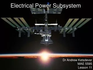
ELECTRICAL POWER AC MOTOR & DC MOTOR
AC MOTOR a. Front Cover e. Back Cover i. Ball Bearings b. Stator Coil f. Fan j. Shaft c. Stator g. Frame d. Terminal Box h. Squirrel Cage Armature
BASIC PART OF AC MOTOR STATOR The function is to supply rotational magnetic field to the rotor. The magnetic field is produced by 2 types of winding:- Starter windings – to determine the direction or rotation of the motor Running winding – to determine the speed of the rotation. Both windings are connected in parallel to the supply source The size and number of windings depends on the use of the motor.
BASIC PART OF AC MOTOR ROTOR The rotor does not have any winding The rotor of an AC induction motor is cylindrical as shown in Figure (a) made of copper or aluminium bars arranged to form a squirrel case. The ends of the bars are soldered together to a ring as shown in Figure (b) The bars allow induced current to flow in the rotor due to the changing magnetic field in the stator. The core of the rotor is made of laminated iron sheets as shown in Figure (c)
OPERATION OF A SINGLE PHASE INDUCTION MOTOR • The basic operation for a single phase induction motor is to generate a rotating magnetic field. • The magnetic field is generated by generating two currents of different phase angle. These currents have 90̊ phase shift. • To produce a rotating magnetic field, the running winding and the starter windings are wound to two pairs of poles in the starter as shown in Figure (a).
In reference to Figure (b), the main current, It will be divided into the starter current, IS and running current, IR. • The difference in the wire size and in the number of windings for construction of the windings will produce a phase difference between the currents in each winding. • The combination of these two currents will cause the stator to generate a rotating magnetic field in the stator and magnetic field of the rotor will cause the rotor to rotate.
TORQUE GENERATION • The AC power supply supplies the magnetic field to the stator. • From the starter winding and the running winding, a rotating magnetic field is generated at the stator. • When current starts to flow in the rotor conductor bars, a magnetic field is generated by the rotor. • The interaction between the magnetic fields of the stator and the rotor will generate a torque in the rotor conductor bars. • This torque produces the rotation of the motor.
TORQUE GENERATION • The AC power supply supplies the magnetic field to the stator. • From the starter winding and the running winding, a rotating magnetic field is generated at the stator. • When current starts to flow in the rotor conductor bars, a magnetic field is generated by the rotor. • The interaction between the magnetic fields of the stator and the rotor will generate a torque in the rotor conductor bars. • This torque produces the rotation of the motor.
THANK YOU ANY QUESTIONS?