Download

1 / 24
240 likes | 241 Views
Battery Charging System for Toy Truck. Capstone Design Project Spring 2007. AKA: Chain Saw. Team #4: Staff. BSEE BSEE BSEE BSEE. Kassie Shore Mark Noller Eric Fitch Josh Siehoff. Team #4: Expertise & Experience.

E N D
Battery Charging System for Toy Truck Capstone Design Project Spring 2007 AKA: Chain Saw
Team #4: Staff • BSEE • BSEE • BSEE • BSEE Kassie Shore Mark Noller Eric Fitch Josh Siehoff
Team #4: Expertise & Experience • Expertise: Soldering, PLC Programming, Project Manager • Experience: 4 Coop Semesters at B&S • Expertise: Soldering, EMC • Experience: 4 year at Harley • Expertise: Soldering, Microcontroller, Elec/Mech Tech • Experience: Military, Industrial Tech • Expertise: Flying Planes • Experience: Pilot Kassie Shore Mark Noller Eric Fitch Josh Siehoff
Team #4: Weekly Availability Worksheet • 15-20 hrs/week • 15-20 hrs/week • 20 hrs/week • 15 hrs/week Kassie Shore Mark Noller Eric Fitch Josh Siehoff
Team #4: Weekly Project Meeting Plan Weekly Meeting 1: UWM, Wednesday 5:00-6:30 PM Kassie, All, Discuss Roles and Project Ideas Weekly Meeting 2: UWM, Wednesday 5:00-6:30 PM Kassie, All, Needs for Project and Start Design Weekly Meeting 3: UWM, Wednesday 5:00-6:30 PM Kassie, All, Continue Design and Split up the Project Weekly Meeting 4: UWM, Wednesday 5:00-6:30 PM Kassie, All, TBD Weekly Meeting 5: UWM, Wednesday 5:00-6:30 PM Kassie, All, TBD Weekly Meeting 6: UWM, Wednesday 5:00-6:30 PM Kassie, All, TBD
Team #4: Total Resources • 60 hrs/week • $100-$1000+ pending sponsorship
Team #4: Decision Making • Our team will make decisions by consensus. • If we can not come to a consensus, we will seek our Lab Assistant. • The last option in our decision making process will be the Professor/Lecturer.
Emergency Vehicle Early Warning System Control Unit Heads-Up Display • Product Description • Alerts traffic to oncoming emergency vehicles. • Control unit on emergency vehicles turns on when siren and lights are active. • Receiver and heads-up display are automatic. • Benefits • Increases time for motor vehicle get out of the way. • Decreases Emergency vehicles response time. • Major External Electrical and User Interfaces • Heads-up Display • Power switches • Mute/Activate button • External Power Inputs and Outputs • Uses 12 VDC vehicle power • RF signal output/transmitter Transmitter Receiver Power Source Power Source
Game Whistle Clock Synchronizer Whistle/Sensor Clock Control • Product Description • Synchronizes the referee whistle and the scorers clock • When the whistle is blown to stop play the clock will automatically stop • When the whistle is blown to start play the clock will automatically stop • Benefits • Eliminates the human time delay • Improves the integrity of the game. • Major External Electrical and User Interfaces • Whistle • On/Off switch • Clock control on scorer’s table • External Power Inputs and Outputs • Power source for whistle is 12VDC battery • Power source for scorers station is 120VAC with set down transformers. Transmitter Receiver Power Source Power Source
Electronic Fuel Tank Switching Unit Fuel Level Sensor Digital Screen Battery Tank Switching Unit • Product Description • This unit would switch between fuel tanks in a small general aviation aircraft based on a timer input from the user. In the event that a tank gets too low for safe operation, the unit would automatically switch tanks. • Benefits • This unit would alleviate some workload in the cockpit. • The device would also eliminate errors in forgetting to switch tanks preventing fuel starvation. • Major external electric & user interfaces • The user interface would be a digital screen allowing the user to enter in the amount of time that they wanted to burn off of each tank. Thirty minutes would be entered if the user wanted to switch fuel tanks every half an hour. • The electronic unit would have a manual override. • External Power Inputs and Outputs • Power would be supplied by the 12-volt system that is standard to small aircraft
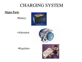
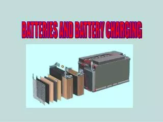
Battery Charging System for Toy Truck Power Supply • Product Description • Toy truck battery charger • Slow trickle charge through induction connection • Benefits • Rechargeable battery more cost effective • Eliminates the need for additional connections to charge battery • Major External Electrical and User Interfaces • LEDs display the amount of time the battery has been on charge. • Inductive coils used for wireless charging. • External Power Inputs and Outputs • Power source on toy is the vehicle power • Induction loops pass the current to the toy vehicle for charging the batter Control Inverter Inductive Coils
Project Selection • Project was selected because funding exists and completion is feasible. The scope of the project can be adjusted with minimal difficulty. The size of the project fits the team size and interests. • The major risks are in dealing with batteries and antennas. • The other projects were rejected due to lack of funding and inability to scope the project. • The project was unanimously supported by the team.
Proposed Product SummaryBattery Charging System for Toy Truck • This battery charging system will allow the user to trickle charge without physical connections to the toy truck. • Primary benefit is to charge without having to physically connect to the charging system. • Other benefits: • Shows the length of time the battery has been on charge. • Quick, easy to use • Low maintenance • Intended application is to charge the battery on the truck for extended use. • The truck becomes fully automatic without having to connect up to the charging system. • The induction charging system is an unique idea. • Automotive/Entertainment/Promotional Industries
Vehicle Battery Charger Power Supply Inverter Induction Loops Vehicle Connection Control w/LED Display
Market Material Cost: $100 Manufacturing Cost: $50 Power Energy Source: AC Voltage Range: 102VAC – 132VAC Power: 1200W Mechanical Energy Source Connector: NEMA 5-15 Environmental Min Oper Ambient Temp Range: 0 – 50C Min Oper Ambient Humidity Range: 0 – 85% Min Storage Ambient Temp Rang: -20 – 70C Min Storage Ambient Humidity Range: 0 – 90% RequirementsSystem – Standard Requirements
Safety Must comply with Part 15 of the FCC Rules regarding radio frequency devices Manufacturing Part count is undetermined Life Cycle Service Strategy Repair at factory Product disposal Return to manufacturer RequirementsSystem – Standard Requirements Cont.
User Inputs Input: Push Button User Indicators & Displays Indicator 1: Information Indicator 1 type: Binary Binary Indicator Technology: LEDs Operation Modes Power Modes: On, Off, Standby Function Modes: Charging Safety Power Signal Ground Fault Max: 6 mAmps Power Signal GF Max Trip Time: 16 msecs RequirementsSystem – Performance Requirements
Block 1 – Power SupplyOwner - Kassie • Power Signals • Input: • AC • Nominal Voltage: 120V , Range: 10.2V – 13.2V • Nominal Frequency: 60Hz, Range: 57Hz – 63Hz • Maximum Current: 10A • Output: • DC • Nominal Voltage: 12V, Range: 11.60V – 12.60V • V ripple: 0.2V • Maximum Current: 20A • Digital Signals • N/A • Analog Signals • N/A
Block 2 – InverterOwner - Josh • Power Signals • Input: • DC • Nominal Voltage: 12V , Range: 10.2V – 13.2V • Maximum Current: 20A • Output: • AC • Nominal Voltage: 24V, Range: 0V – 48V • Maximum Current: 10A • Nominal Frequency: 400 Hz, Range: 100-500Hz • Digital Signals • Input • Frequency Input • Nominal Frequency: 400Hz, Range: 100-500Hz • 5V Logic Voltage • Analog Signals • Output • Frequency Control • Nominal Frequency: 60Hz, Range: 51-66Hz • Voltage Max Amplitude: 14.5V
Block 3 – ControlOwner - Eric • Power Signals • Input: • DC • Nominal Voltage: 12V , Range: 11.0V – 14.5V • Nominal Frequency: N/A • Maximum Current: 1A • Digital Signals • Output: • DC (frequency control) • Nominal Voltage: 5V, Range 2.4V- 5.5V • Nominal Frequency:400hz Pulse (control signal) • Maximum Current: 1A • DC (LED Display) • Nominal Voltage:5V. Range 2.4V-5.5V • Maximum Current 100mA • Analog Signals • Input: • DC • Nominal Voltage: 12V , Range 11.0V – 14.5V • Maximum current: 1.0A
Block 4 – Inductive LoopsOwner - Mark • Power Signals • Input: • AC • Nominal Voltage: 24V , Range: 0V – 48V • Nominal Frequency: 400Hz, Range: 100Hz – 500Hz • Maximum Current:10 A • Output: • DC • Nominal Voltage: 13.8V, Range: 13.0V – 14.0V • V ripple: .2V • Maximum Current:30 A
Patents • US PN 6,972,543 • Series resonant inductive charging circuit • December 6, 2005 • US PN 5,694,023 • Control and termination of a battery charging process • December 2, 1997 • US PN 6,940,257 • Battery charger • September 6, 2005
Ethical or Societal Issues • One issue that we have to address is to prevent too much current from entering the battery on the toy car during the charging process. • Another issue that we have to address is to make sure there is sufficient shielding around the coils.