Download
1 / 27
270 likes | 385 Views
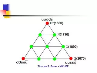
[R. Alemany] [CERN AB/OP] [Engineer In Charge of LHC] Lectures at NIKHEF (12.12.2008). The Large Hadron Collider Contents: 1. The machine II. The beam III. The interaction regions IV. First LHC beam. III. The interaction regions. Contents: The straight sections.

E N D
[R. Alemany] [CERN AB/OP] [Engineer In Charge of LHC] Lectures at NIKHEF (12.12.2008) The Large Hadron ColliderContents:1. The machineII. The beamIII. The interaction regionsIV. First LHC beam
III. The interaction regions Contents: • The straight sections • Betatron and momentum cleaning insertions • The experiments: • High luminosity insertions (ATLAS & CMS) • Low luminosity insertions (ALICE & LHCb) • Squeeze • Colliding with a crossing angle • Luminosity optimization
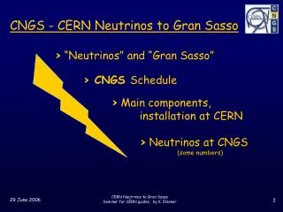
III.I. The straight sections IT IT IP SPS (~7 km) LHC (27 km) Sector IR MS DS IR ARC
III.I. The straight sections • A straight section is composed of: • Matching section (MS) • Inner triplets (IT) ( there is an experiment) • IR: collimators, RF, dump system, experiments
III. The interaction regions Contents: • The straight sections • Betatron and momentum cleaning insertions • The experiments: • High luminosity insertions (ATLAS & CMS) • Low luminosity insertions (ALICE & LHCb) • Luminosity optimization
III.II Momentum and betatron cleaning insertions (IR3, IR7) (collimators are not shown) Particles with large momentum offset are scattered by the primary collimators in IR3. Particles with large H, V or H&V betatron amplitudes are scattered by the primary collimators in IR7. In both cases the scattered particles are absorbed by secondary collimators. Typical quadrupole strength 30-35 T/m Q4 Q5 D3 D4 Q6 Q7 IR3 224 mm Warm magnets (collimators are not shown) IR7 Note: IR3 & IR7 have special DS (arc quadrupoles in series + trim quadrupoles) because of lack of space to place the power converters.
III.II Momentum and betatron cleaning insertions (IR3, IR7) 50 14 7 8.5 6(9) Settings @7TeV and *=0.55 m Beam size () = 300 µm (@arc) Beam size () = 17 µm (@IR1, IR5)
III. The interaction regions Contents: • The straight sections • Betatron and momentum cleaning insertions • The experiments: • High luminosity insertions (ATLAS & CMS) • Low luminosity insertions (ALICE & LHCb) • Squeeze • Colliding with a crossing angle • Luminosity optimization
III.III The experiments: High luminosity insertions • The high luminosity insertions are IR1 (ATLAS) and IR5 (CMS) • They are identical in terms of hardware and optics • The optics design is guided by two main requirements: • Large dynamic range of * values while keeping the total phase advance over the IR constant: • * = 18 m for injection • * = 0.55 m for collisions • When changing from injection to collision optics, the quadrupole magnets must change smoothly with * to have under control the beam size, the beam separation and the chromaticity
III.III The experiments: High luminosity insertions • The hardware constraints: • The beams share the same beam pipe and the same low beta triplet quadrupoles, so the optics solution must have the same triplet gradients. The maximum gradients are constraint • The overall beam size must be small enough to fit into the tight aperture of the LHC at this location • Optics: * The beams at pre-collision are displaced from the ideal orbit to increase the mechanical aperture of the low beta triplet quadrupoles ** phase advance for the whole insertion region (Q13.R – Q13.L)
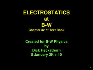
III.III. The experiments: High luminosity insertions Inner Triplet Separation/ Recombination Matching Quadrupoles ATLAS R1 Tertiary collimators Q7 Q1 Q2 Q3 D1 (1.38 T) D2 Q4 (3.8 T) Q5 Q6 TAN* TAS* IP1 188 mm 1.9 K Warm 1.9 K 4.5 K 4.5 K 4.5 K 6.45 kA 10.63 kA Q2 Q3 Q1 29.0 24.0 22.5 17.6 23.85 18.95 To provide sufficient aperture for the Xangle * Protect Inner Triplet (TAS) and D2 (TAN) from particles coming from the IP The mechanical aperture of the inner triplets limits the maximum * @IPs and the maximum Xangle limit peak lumi
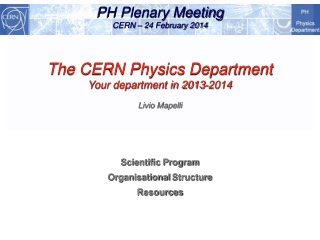
ATLAS CMS five-storey building III.III. The experiments: High luminosity insertions
III.III. The experiments: Low luminosity insertions ALICE LHCb LHCb Q1 Q2 Q3 D1 D2 Q4 Q5 Q6 Q7 TCDD IP8 TDI Beam 2 Beam 1 MSI MKI Beam 2 Beam 1
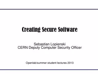
LHCb experiment Center of the exp cavern
III.III. The experiments: Low luminosity insertions ALICE LHCb
III. The interaction regions Contents: • The straight sections • Betatron and momentum cleaning insertions • The experiments: • High luminosity insertions (ATLAS & CMS) • Low luminosity insertions (ALICE & LHCb) • Squeeze • Colliding with a crossing angle • Luminosity optimization
III.IV. Squeeze • Squeeze: change quadrupole currents (magnet strength) in a way that the beta function at the interaction point is very small to increase luminosity • Magnets: matching quadrupoles RB RQD/RQF
III.IV. Squeeze Squeeze the beam size down as much as possible at the collision point to increase the chances of a collision • So eventhoughwe squeeze our100,000 million protons per bunch down to 16 microns (1/5 the width of a humanhair) at the interaction point. Wegetonlyaround 20 collisions per crossingwith nominal beamcurrents. • The bunches cross (every 25 ns) sooftenwe end up witharound600 million collisions per second - at the start of a fillwith nominal current. • Most protons miss eachother and carry on around the ring. The beams are keptcirculating for hours 10 hours
III.IV. Squeeze Beta function at top energy and after squeeze IR1 IR5 IR1 Injection IR3 IR4 IR2 IR6 IR7 IR8
III.IV. Squeeze IT MS DS Q1 Q3 D2 Q5 Q7 Q8 Q9 Q10 Q11 D1 Q4 Q6 Q2 2MB 2MB 2MB 2MB ATLAS=CMS
III. The interaction regions Contents: • The straight sections • Betatron and momentum cleaning insertions • The experiments: • High luminosity insertions (ATLAS & CMS) • Low luminosity insertions (ALICE & LHCb) • Squeeze • Colliding with a crossing angle • Luminosity optimization
III.IV Colliding with a Xangle Why? to minimize beam-beam interaction effects Vertical Xangle (160 µrad @ injection, 142.5 µrad @collis) Horizon Xangle (160 µrad @ injection, 142.5 µrad @collis)
III. The interaction regions Contents: • The straight sections • Betatron and momentum cleaning insertions • The experiments: • High luminosity insertions (ATLAS & CMS) • Low luminosity insertions (ALICE & LHCb) • Squeeze • Colliding with a crossing angle • Luminosity optimization
x s Φ ρ1(x,y,s,-s0) ρ2(x,y,s,-s0) III.IV Luminosity optimization Ni = number of protons/bunch Nb = number of bunches frev = revolution frequency ix = beam size along x for beam i iy = beam size along y for beam i Assume Gaussian distributions for the beam distribution functions and equal bunch length. • Luminosity formulae: F is a pure crossing angle (Φ) contribution, which for a crossing angle in the horizontal plane (XS, with S the direction of movement) takes the form: FLHC = 0.836 W is a pure beam offset contribution. If the offset is in the horizontal plane beam 1 is displaced by d1 and beam 2 is displaced by d2 with respect to their reference orbits, thus W takes the form:
III.IV Luminosity optimization exp(B2/A) is a term that appears when beams collide with a crossing angle and an offset at the same time. For a crossing angle and an offset in the x direction: Luminosity monitors in the machine BRAN detectors: Luminosity scans: 1: Get the beams into collision (the first days of beam commissioning); 2: Optimize luminosity every fill 3: Calibrate luminosity based on machine parameters dedicated runs Each of these is of course applicable at each of the four LHC interaction points.
III.IV Luminosity optimization • Method orthogonal separation scans y x Example from LEP
III.IV Luminosity optimization • Luminosity ≠ cte over a physics run. It decays due to degradation of intensities and emittance. • The main cause of lumi decay are the collisions themselves, but there are other contributions like beam-gas scattering, beam-beam interactions • ~ 15 hours (lumi lifetime) • 600 million collisions/sec = 20 coll/crossx2808x11000Hz • Raw data rate is 1015 bytes/sec • equivalent to >1 million CD-roms/sec • Only 0.00025% recorded for analysis • experimental “trigger” rejects the rest