Download
1 / 28
280 likes | 283 Views
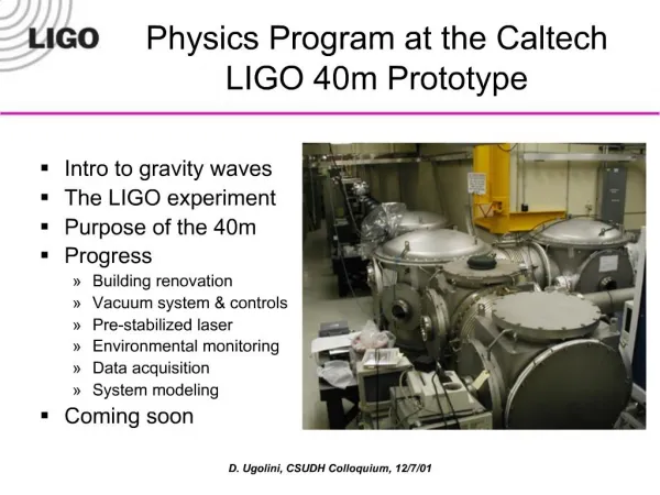
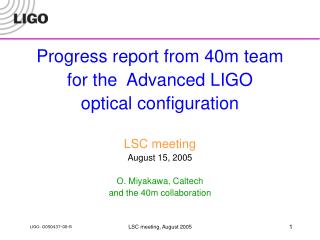
Report to the 40m Technical Advisory Committee October 13, 2005 The 40m Team Ben Abbott, Rana Adhikari, Dan Busby, Jay Heefner, Osamu Miyakawa, Mike Smith, Bob Taylor, Monica Varvella, Steve Vass, Rob Ward, Alan Weinstein

E N D
Report to the 40m Technical Advisory Committee October 13, 2005 The 40m Team Ben Abbott, Rana Adhikari, Dan Busby, Jay Heefner, Osamu Miyakawa, Mike Smith, Bob Taylor, Monica Varvella, Steve Vass, Rob Ward, Alan Weinstein with lots of help from: Matt Evans, Helena Armandula, Rolf Bork, Alex Ivanov, SURF students, etc… 40m TAC, 10/13/05
Status as of October 2005 • Slides 3 through 11: presented at August LSC meeting, included for your review, skip for now. • Status of lock acquisition (Rob, Osamu, Matt, Rana) • e2e simulation (Monica) • DC readout (Smith, AJW, all) • Proposal for squeezing-enhanced gravitational wave interferometer at the 40m (Nergis) 40m TAC, 10/13/05
Caltech 40 meter prototype interferometer Objectives • Develop lock acquisition procedure of detuned Resonant Sideband Extraction (RSE) interferometer, as close as possible to AdLIGO optical design • Characterize noise mechanisms • Verify optical spring and optical resonance • Develop DC readout scheme • Extrapolate to AdLIGO via simulation BS SRM PRM Bright port Dark port X arm Y arm 40m TAC, 10/13/05
Carrier (Resonant on arms) -f2 -f1 f1 f2 AdLIGO signal extraction scheme ETMy • Mach-Zehnder installed to eliminate sidebands of sidebands. • Only + f2is resonant on SRC. • Unbalanced sidebands of +/-f2 due to detuned SRC produce good error signal for Central part. • Arm cavity signals are extracted from beat between carrier and f1 or f2. • Central part (Michelson, PRC, SRC) signals are extracted from beat between f1 and f2, not including arm cavity information. 4km f2 ITMy ETMx PRM ITMx BS 4km f1 SRM • Single demodulation • Arm information • Double demodulation • Central part information 40m TAC, 10/13/05
5 DOF for length control Signal Extraction Matrix (in-lock) ETMy Phase Modulation f1=33MHz f2=166MHz Ly=38.55m Finesse=1235 ITMy Common of arms Differential of arms Power recycling cavity Michelson Signal recycling cavity : L=(Lx Ly) / 2 : L=Lx Ly : l=(lx ly) / 2 =2.257m : l=lx ly = 0.451m : ls=( lsx lsy) / 2 =2.15m GPR=14.5 lsy ETMx Laser ly ITMx BS lx Lx =38.55m Finesse=1235 PRM lsx T=7% SRM T=7% PO SP AP 40m TAC, 10/13/05
Differences betweenAdvLIGO and 40m prototype • 100 times shorter cavity length • Arm cavity finesse at 40m chosen to be = to AdvLIGO ( = 1235 ) • Storage time is x100 shorter. • Control RF sidebands are 33/166 MHz instead of 9/180 MHz • Due to shorter PRC length, less signal separation. • LIGO-I 10-watt laser, negligible thermal effects • 180W laser will be used in AdvLIGO. • Noisier seismic environment in town, smaller stack • ~1x10⁻⁶m at 1Hz. • LIGO-I single pendulum suspensions are used • AdvLIGO will use triple (MC, BS, PRM, SRM) and quad (ITMs, ETMs) suspensions. 40m TAC, 10/13/05
Carrier 33MHz 166MHz ITMy Carrier ITMx BS Unbalanced 166MHz PRM DDM PD 33MHz SRM DDM PD OSA DDM PD Belongs to next carrier Belongs to next carrier DRMI lock using double demodulation with unbalanced sideband by detuned cavity August 2004 • DRMI locked with carrier resonance (like GEO configuration) November 2004 • DRMI locked with sideband resonance (Carrier is anti resonant preparing for RSE.) Typical lock acquisition time : ~10sec Longest lock : 2.5hour 40m TAC, 10/13/05
(POX/TrX), (POY/TrY) (POX/TrX) + (POY/TrY), (POX/TrX) – (POY/TrY) Carrier 33MHz 166MHz SP166/PRC, AP166/PRC (TrX + TrY), (TrX – TrY) / (TrX + TrY) Lock acquisition procedure towards detuned RSE Ideas for arm control signal Off-resonant arms using DC lock DRMI using DDM RSE ETMy Shutter ITMy PRM ETMx ITMx BS Shutter SRM Done Done In progress 40m TAC, 10/13/05
Arm power Xarm lock Yarm lock Error signal Offset lock Offset lock Ideal lock point All 5 degrees of freedom under controlledwith DC offset on L+ loop Both arms locked with DRMI • Lock acquisition time ~1 min • Lasts ~ 20 min • Can be switched to common/differential control L- : AP166 with no offset L+ : Trx+Try with DC offset Have started trying to reduce offset from L+ loop But… 40m TAC, 10/13/05
Progress in last 6 months • For the last 6 months , we have been able to control all 5DOF, but with CARM offset. • Reducing the CARM offset has been made difficult by technical noise sources. We have spent last 6months reducing them; • suspension noise, vented to reduce couplings in ITMX • improved diagonalization of all suspensions • improved frequency noise with common mode servo • automation of alignment and lock acquisition procedures • improved DC signals and improved RF signals for lock acquisition. • We can now routinely lock all 5 DOFs in a few minutes at night. 40m TAC, 10/13/05
RSE peak! • Optical gain of L- loop • DARM_IN1/DARM_OUT divided by pendulum transfer function • No offset on L- loop • ~60pm offset on L+ loop • Phase includes time delay of the digital system. • Optical resonance of detuned RSE can be seen around the design RSE peak of 4kHz. • Q of this peak is about 7. • Effectively the same as Full RSE with GPR=1.4 with 1W input laser. • Model was calculated by Thomas’s tool. • We will be looking for optical spring peak. Design RSE peak ~ 4kHz 40m TAC, 10/13/05
Lock acquisition procedure towards detuned RSE Start with no DOFs controlled, all optics aligned. Re-align each 1.5 hours. ITMy 166MHz ITMx 13m MC BS 33MHz PRM PO DDM SP33 SRM SP166 SP DDM AP166 AP DDM 40m TAC, 10/13/05
1/sqrt(TrY) Lock acquisition procedure towards detuned RSE DRMI + 2arms with offset Average wait : 1 minute (at night, with tickler) ITMy 166MHz ITMx 13m MC 1/sqrt(TrX) BS 33MHz PRM T=7% PO DDM SRM SP166 SP33 T=7% I SP DDM Q AP166 AP DDM 40m TAC, 10/13/05
-1 Lock acquisition procedure towards detuned RSE Scripto-matic: Short DOFs -> DDM DARM -> RF signal CARM -> DC signal 1/sqrt(TrX)+ 1/sqrt( TrY) Discretionary: CARM CARM -> Digital CM_MCL servo + + DARM ITMy 166MHz ITMx 13m MC BS 33MHz PRM PO DDM SRM SP33 SP166 SP DDM To DARM AP166 AP DDM AP166 / (TrX+TrY) 40m TAC, 10/13/05
-1 Lock acquisition procedure towards detuned RSE Reduce CARM offset: Up next: Go to higher ARM power, switch on AC-coupled analog CM_AO servo, using REFL DC as error signal. Locks somewhat stable at 85% of maximum power. RF control of CARM: REFL166 (POX/POY 33 ?) DARM ITMy 166MHz GPR=5 ITMx 13m MC BS SP166 33MHz PRM PO DDM SRM SP33 SP DDM To DARM REFL AP166 AP DDM AP166 / (TrX+TrY) 40m TAC, 10/13/05
Ready for Transition to RF CARM 40m TAC, 10/13/05
Progress in last 2 months • Use CARM DC signal to creep closer to full arm resonance (signal goes away at resonance) • combined PRC and arm gain as high as 60, 85% of the way to peak, corresponding to offset of 8 pm, assuming arm losses of 200ppm (inferred). • Progress due largely to improvements in loop filtering, to obtain more gain and reduce noise • Significant improvements in automation of lock procedures. • All DOFs diagonalized: 3x3 (SRC/PRC/MICH) + 2x2 (DARM/CARM) • Lock is lost because of large frequency noise (presumably). • Effort to reduce frequency noise using CM servo • digital CM servo to MC works well • analog servo using DC signal seems to work, RF under development • frequency noise may be coming from in-vac PZTs. Not beam jitter noise. • Much effort to reduce other noise sources • better diagonalization of MC suspensions, core optics suspensions • continual battle with 60 Hz harmonics 40m TAC, 10/13/05
Development of e2e simulation:4Om/AdvLIGO package • Monica Varvella (visitor from LAL/Orsay) has developed a 4Om/AdvLIGO package with a DRFPMI optical plant, and is developing the control plant with help from Matt Evans and Hiro Yamamoto • Tests include a careful comparison with Twiddle, as well as comparison of error signal sweeps between simulation and 40m data. • Can be used to extract the velocity of the mirrors in the 40m under controlled circumstances: lock all degrees of freedom, CARM offset, and then HOLD the CARM servo and watch error signal as mirrors sweep through arm resonance. 40m TAC, 10/13/05
e2e SIMULATION:4Om/AdvLIGO package Error signal sweeps at 10-9 m/s for the 40m IFO obtained in E2E framework and compared with TWIDDLE predictions TWIDDLE E2E Example: DARM @ AP166 MHz TWIDDLE and E2E comparison 40m TAC, 10/13/05
e2e SIMULATION:4Om/AdvLIGO package Real data have been used to estimate relative mirror velocity for both the arms: Vxarm= (0.35 ± 0.13)μm/s Vyarm= (0.26 ± 0.13)μm/s Tr X E2E real data Comparison between real data (black) and e2e simulated data (red) of the transmitted light for both the arms (full IFO): the mirror velocities used in E2E simulation are the values obtained fitting the real data Tr Y real data E2E 40m TAC, 10/13/05
e2e SIMULATION:4Om/AdvLIGO package Comparison between real data , e2e simulated data and the theoretical prediction V(t) of the SP error signal @ 166 MHz V(t) ~ exp(t/τ) sin( a t2) with a = (k v) / (2 T) The τand the velocityvis the value obtained fitting real data τ = 0.7 ms v = 0.26 μm/s 40m TAC, 10/13/05
DC Readout at the 40m • DC Readout eliminates several sources of technical noise (mainly due to the RF sidebands): • Oscillator phase noise • Effects of unstable recycling cavity. • The arm-filtered carrier light will serve as a heavily stabilized local oscillator. • Perfect spatial overlap of LO and GW signal at PD. • DC Readout has the potential for QND measurements, without major modifications to the IFO. • We may not be able to see shot noise at low frequency, given our noise environment. We may not even see any noise improvements, but we might! • The most important thing we will learn is : How to do it • How to lock it? • How best to control the DARM offset? • What are the unforeseen noise sources associated with an in-vacuum OMC? • How do we make a good in-vac photodiode? What unforeseen noise sources are associated with it? 40m TAC, 10/13/05
DC readout equipment • Most in-vac optics and opto-mechanics have been ordered • Most mirror mounts and mirrors • Output mode-matching telescope with picomotor focus • two Piezo-Jena steering mirrors • but NOT the PZT drivers. Jay Heefner has committed to designing these (also maybe needed at sites for RBS system). Design based on IO PZTs. Need strain gauge readback. • OMC design from Mike Smith • 4-mirror design • super-mirrors with REO coatings coming from LIGO Lab spares • DC PD assembly and electronics under design (Abbott, Adhikari) • OMC control, DC PD readout, and monitoring electro-optics and readout, under design (Heefner), mostly using existing infrastructure and equipment. • Alignment on bench, in air, and in vacuum seem feasible. 40m TAC, 10/13/05
Output Optical Train 1st PZT steering mirror gets a little tight around IMMT SRM 2nd PZT steering mirror BSC OOC IOC Mike Smith 40m TAC, 10/13/05
Output Optic Chamber Existing in-vac seismically isolated optical table (OOC) to OMCR beamline Mike Smith has designed a compact, monolithic MMT, similar to our input MMT, using spherical mirrors. 4-mirror monolithic OMC. Pair of DC PDswith in-vac electronicson monolithic base. from SRM 2nd PZT steering mirror PZT steering mirrors and their controls are duplicates of a pair that we have already installed and commissioned for steering from IMC to main IFO (in-vac); controls are fully implemented in the ASC system (by Rolf). Similar systems can be used for “LIGO I.V”. Piezosystem Jena PSH 5/2 SG-V, PZT tilting mirror mount with strain gauge, and associated drivers and power supplies to OMCT beamline IMCR, IMCT, and SP beamlines to AS RF beamline (roughly 1/3 of AS power) also a convenient path for autocollimator beam, for initial alignment in air from PSL to IMC Mike Smith 40m TAC, 10/13/05
OMC, four mirror design From MMT reflected beam SS fixed spacer ~ 20 cm PZT mirror mechanical clamps (no glue) Mike Smith to DCPD • Mirrors mounted mechanically, on 3 points (no glue) • curved mirror: off-the-shelf CVI laser mirror with ROC = 1 m ± 0.5% • Fixed spacer should be rigid, vented, offset from table • OMC length signal: • Dither-lock? >> Should be simple; we’ll try this first. • PDH reflection? >> There’s only one sideband, but it will still work. • Servo: • Will proceed with a simple servo, using a signal generator and a lock-in amp. • Feedback filters can easily be analog or digital. • Can use a modified PMC servo board for analog. • Can use spare ADC/DAC channels in our front end IO processor for digital. • PZT actuation 40m TAC, 10/13/05
OMC design in SolidWorks • Small number of pieces • HV compatible • a bit of glue on the PZT mirror • Mirrors mounted mechanically, on silver washers (no glue) • ALGOR FEA: lowest mech resonance at ~770 Hz • Construct out of well-damped material, to minimize effect of resonances • Brass? Copper? • Or just stick with aluminum? • All high-quality (REO super-polished and coated) mirrors available from LIGO lab spares (well, the 4th HR mirror, 0o incidence, may need to come from Newport) Mike Smith 40m TAC, 10/13/05
In-vac DC photodiodes Ben Abbott Three views of an in-vacuum DC PD assembly, showing a 50% beamsplitter, two photodiodes, a beam-dump, and a vacuum can to hold electronics. The base will not be made of marble. Electronics under design (Abbott, Adhikari) 40m TAC, 10/13/05